Skip to the content
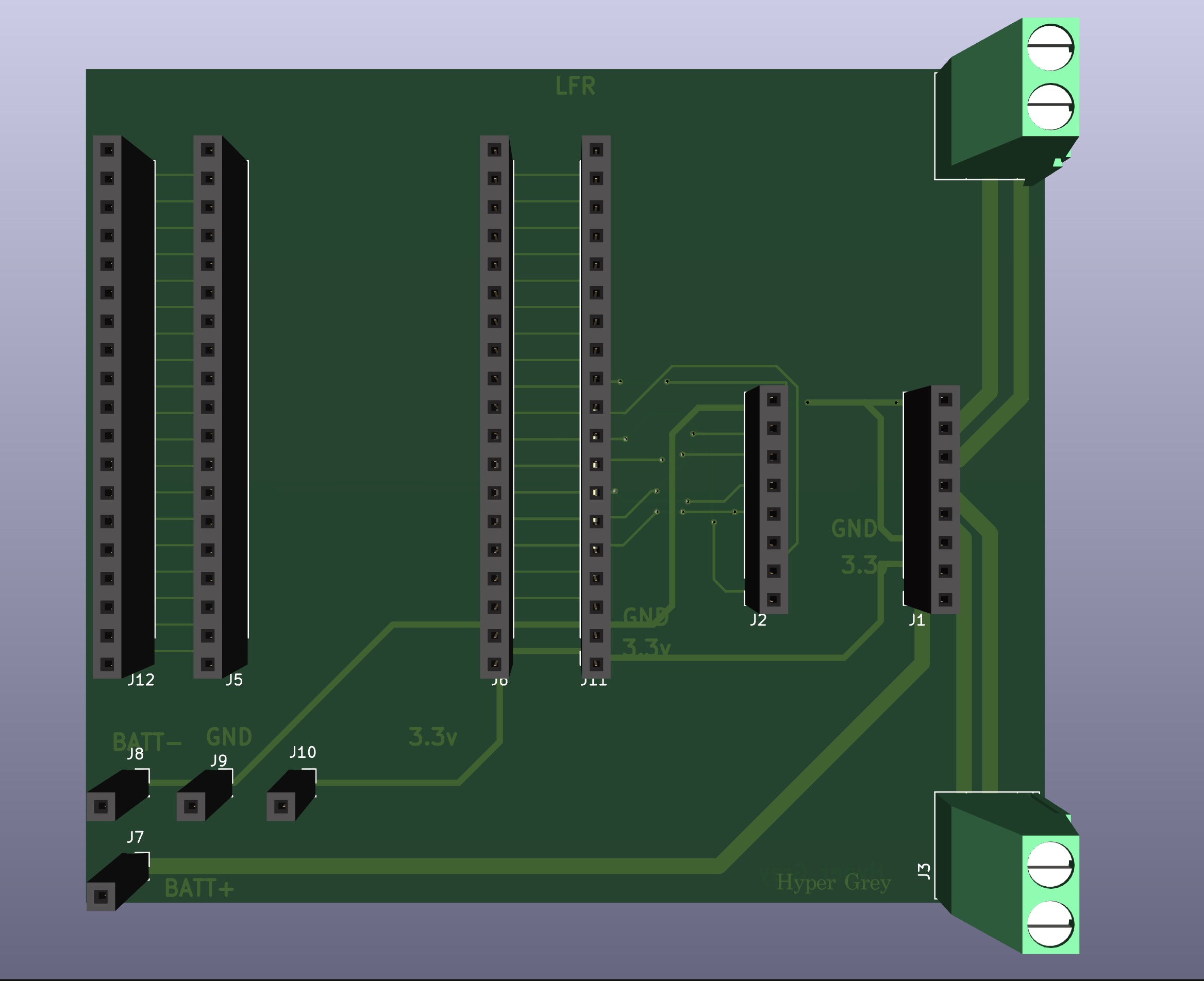
2 layers92 × 80 mmLFR, the printed circuit board in 3D

A custom-designed PCB for a Line Follower Robot (LFR) integrating ESP32, motor driver connections(TB6612FNG), and IR sensor arrays.

Size
92 × 80 mm
Copper layers
2
Thickness
1.6 mm
Parts
12
Nets
43
Pads
100
Tracks, vias
145, 17
Routed
Yes
KiCad
KiCad 9.0 (file 20241229)
Created
18 Apr 2026
Updated
18 Apr 2026

Overview

LFR is an open-source printed circuit board by Pulkit-10-0, from the Pulkit-10-0/LFR-Control-PCB-ESP32 repository on GitHub. It is a 2-layer board of 92 × 80 mm with 12 parts on 43 nets, routed with 145 tracks and 17 vias.

It belongs with the robots and motor control boards of this library.

README

Readme.md

Line Follower Robot (LFR) Control PCB

EDA Domain Type MCU Sensors Status

A custom-designed PCB for a Line Follower Robot (LFR) integrating ESP32, motor driver connections(TB6612FNG), and IR sensor arrays. The board is designed to simplify wiring, improve reliability, and provide a structured layout for robotics prototyping.


Preview

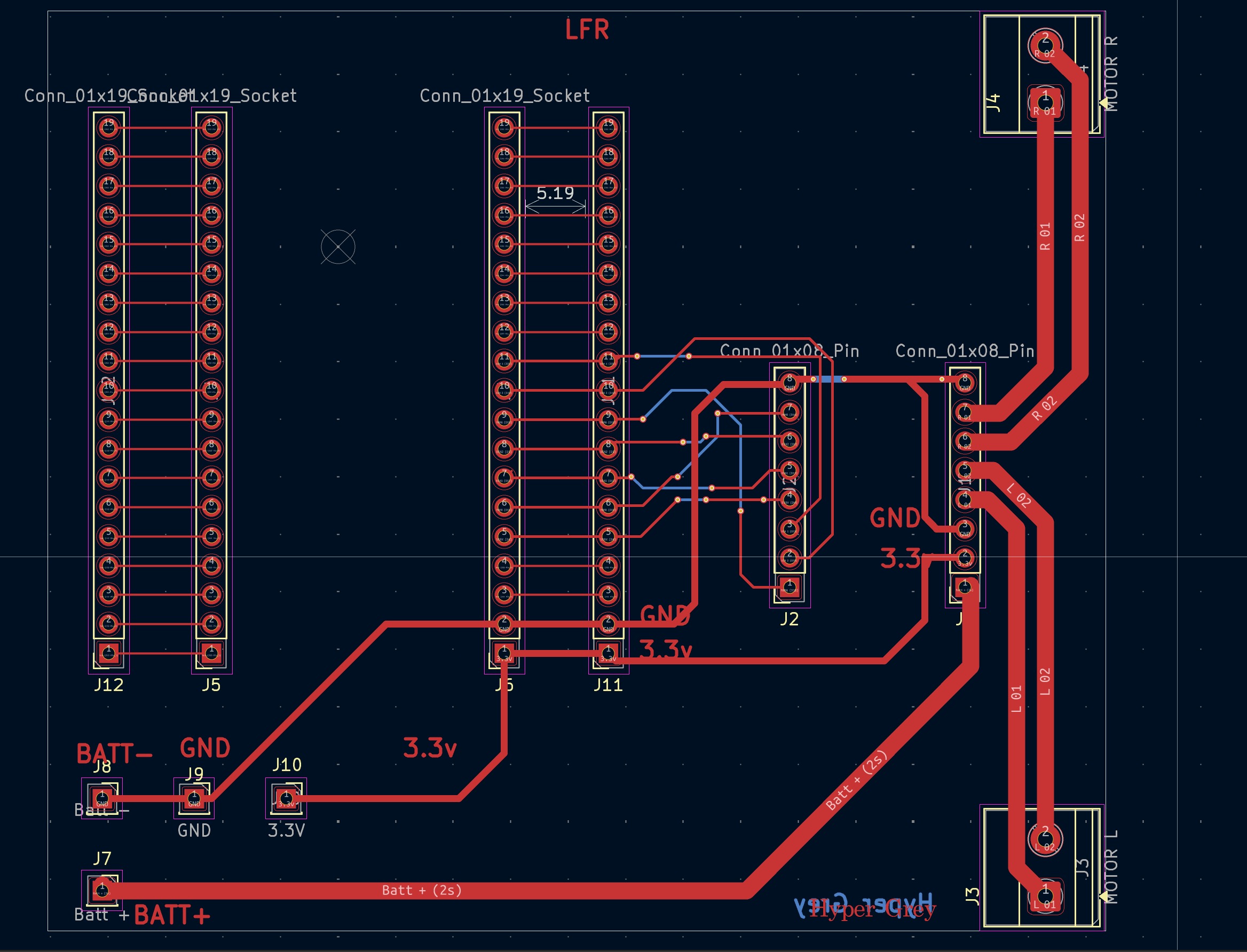
PCB Layout

PCB

3D View (front)

3D

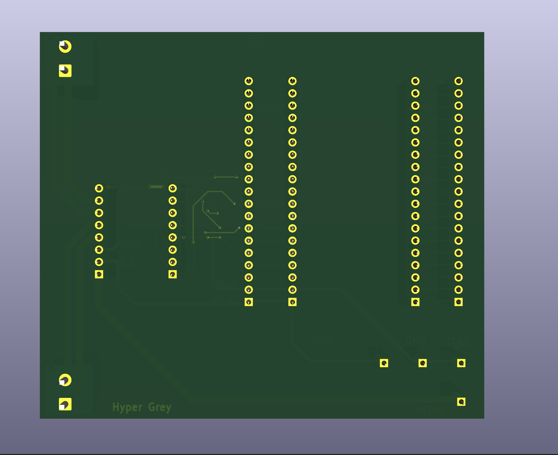
3D View (back)

Routing

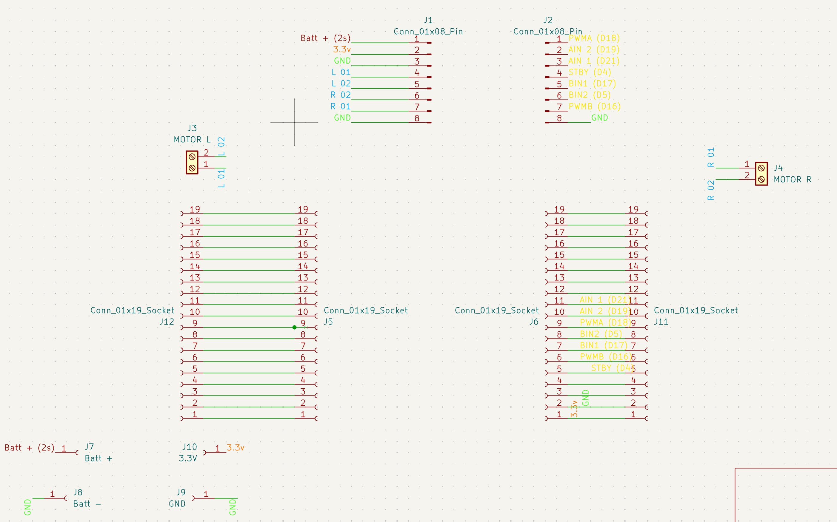
Schematic

Schematic


Features

  • ESP32-compatible dual-row header layout
  • Dedicated connectors for IR sensor arrays
  • Motor driver interface (PWM + direction control)
  • Screw terminals for motor connections
  • Separate power inputs for battery and regulated 3.3V
  • Wide traces for motor current paths
  • Clearly labeled silkscreen for easier debugging

Design Overview

System Architecture

  • ESP32 acts as the main controller
  • IR sensor arrays provide line detection inputs
  • Motor driver module controlled via PWM and direction pins
  • External battery input powers motors and system

Signal Flow

  • Sensor inputs → ESP32 GPIO
  • ESP32 → Motor driver (PWM + control signals)
  • Motor driver → Motors (Left & Right)

Power Design

  • Battery input (2S) routed through dedicated power traces
  • Separate 3.3V rail for logic-level components
  • Common ground shared across all modules
  • Wide traces used for motor current paths to reduce voltage drop

PCB Design Highlights

  • Organized layout based on functional blocks (sensors, MCU, motors)
  • Thick traces for high-current motor lines
  • Short routing paths for control signals
  • Clearly separated power and signal routing (basic level)
  • Connector-based design for modularity

Project Structure

hardware/ ├── LFR.kicad_sch ├── LFR.kicad_pcb └── LFR.kicad_pro

Images/ ├── pcb.png ├── pcb_3d.png ├── pcb_3d_.png └── schematic.png


Learning Outcomes

  • Designing a practical robotics PCB from scratch
  • Understanding power vs signal routing
  • Connector-based modular hardware design
  • ESP32 pin mapping and hardware interfacing
  • Basic PCB layout optimization

Challenges

  • Managing trace width for motor currents
  • Routing multiple GPIO signals cleanly
  • Maintaining clarity in pin mapping
  • Avoiding messy wiring replacement with PCB structure

Limitations

  • No dedicated voltage regulation onboard
  • No ground plane (can be improved)
  • Minimal noise/EMI considerations
  • Designed for prototyping, not production

Future Improvements

  • Add onboard voltage regulator (buck converter)
  • Implement ground plane for better return paths
  • Add mounting holes
  • Improve trace routing and symmetry
  • Add protection circuits (reverse polarity, fuse)

Parts

12
QtyValueFootprintReferences
4Conn_01x19_SocketConnector_PinSocket_2.54mm:PinSocket_1x19_P2.54mm_VerticalJ5, J6, J11, J12
2Conn_01x08_PinConnector_PinSocket_2.54mm:PinSocket_1x08_P2.54mm_VerticalJ1, J2
13.3VConnector_PinSocket_2.54mm:PinSocket_1x01_P2.54mm_VerticalJ10
1Batt +Connector_PinSocket_2.54mm:PinSocket_1x01_P2.54mm_VerticalJ7
1Batt -Connector_PinSocket_2.54mm:PinSocket_1x01_P2.54mm_VerticalJ8
1GNDConnector_PinSocket_2.54mm:PinSocket_1x01_P2.54mm_VerticalJ9
1MOTOR LTerminalBlock_Phoenix:TerminalBlock_Phoenix_MKDS-1,5-2_1x02_P5.00mm_HorizontalJ3
1MOTOR RTerminalBlock_Phoenix:TerminalBlock_Phoenix_MKDS-1,5-2_1x02_P5.00mm_HorizontalJ4

Similar boards

  • 2 layersNrf bga, the printed circuit board in 3D

    Nrf bga

    github-linguist/linguist

    Language Savant. If your repository's language is being reported incorrectly, send us a pull request!

    12 parts14kMIT
  • 2 layers66.9 × 74.5 mmDeskHop, the printed circuit board in 3D

    DeskHop

    hrvach/deskhop

    Fast Desktop Switching Device

    12 parts7.9kGPL-3.0
  • 2 layers40 × 15 mmSensors, the printed circuit board in 3D

    Sensors

    google/mozc-devices

    Circuit diagrams and firmware source code for Gboard DIY keyboards

    12 parts3kApache-2.0
  • 2 layers42.7 × 56.5 mmTle6240 driver, the printed circuit board in 3D

    Tle6240 driver

    rusefi/rusefi

    rusefi - GPL internal combustion engine control unit

    12 parts1.2k
  • 2 layers49 × 25 mm5v boost regulator, the printed circuit board in 3D

    5v boost regulator

    hackclub/OnBoard

    💡 Join 1,000 teenagers and make your first PCB with a $100 grant!

    12 parts915
  • 2 layers28.3 × 10.3 mmTap Photosensor PCB, the printed circuit board in 3D

    Tap Photosensor PCB

    VoronDesign/Voron-Tap

    Tap is a nozzle-based z-probe for the V2 and Trident printer designs. The entire toolhead moves to trigger an optical switch. Tap offers many advantages:

    12 parts716GPL-3.0
  • 2 layers25.4 × 70.4 mmTpmsniffer, the printed circuit board in 3D

    Tpmsniffer

    stacksmashing/pico-tpmsniffer

    A simple, very experimental TPM sniffer for LPC bus

    12 parts696

Questions

How big is the LFR PCB?

It measures 92 × 80 mm and has 2 copper layers, 1.6 mm thick.

What parts does the LFR use?

12 parts. The full list of its parts is on this page, with links to each part's symbol and footprint where PCBKit's library has them.

Where can I download the LFR KiCad files?

From the Pulkit-10-0/LFR-Control-PCB-ESP32 repository on GitHub, at the commit this page was made from: the board is LFR.kicad_pcb and its schematic LFR.kicad_sch. PCBKit opens the board in the browser, with nothing to install.

Can I use the LFR design in my own project?

Its repository states no licence, so its author keeps all rights: ask Pulkit-10-0 before reusing the design.