2 layers99.7 × 67.3 mm

 PPUC/Hardware_IO_16x8_matrix
Hardware for a Switch Matrix Board for PPUC
IO 16x8 matrix is an open-source printed circuit board by PPUC, from the PPUC/Hardware_IO_16x8_matrix repository on GitHub. It is a 2-layer board of 97.6 × 67.3 mm with 210 parts on 147 nets, routed with 1,944 tracks and 522 vias.
It is built around the RP2040, ADM3483ARZ and SN74AHCT1G125DBV, with the LMV321, W25Q128JVSIQ and LM339 among its other parts. Its parts include 92 resistors, 58 capacitors, 23 diodes, 10 ICs and 9 connectors. It belongs with the lEDs and displays boards and the RP2040 boards of this library.


This is the hardware for a 16x8 switch matrix card which was designed for the PPUC pinball project, but can be useful in other applications as well. The intentionally usecase is to connect an original equipped pinball playfield (including cable harness and diodes). Normally I'd prefer direct switches but if all the switches and cables and diodes are in place already, it is useful to connect the switch matrix directly. The board can also be used for 16 direct inputs and 8 low power signal-outputs (no matrix).
It is designed for being low cost and functional for experimental use.
Not everything is tested nor does it fulfill EMC or any other specifications.
Use at your own risk!
To make use of anything of this project a basic understanding of electronics and programming is necessary. Nothing of it is "plug and play". I'm surely not liable for any damage to assemblies, pinball machines or even persons.
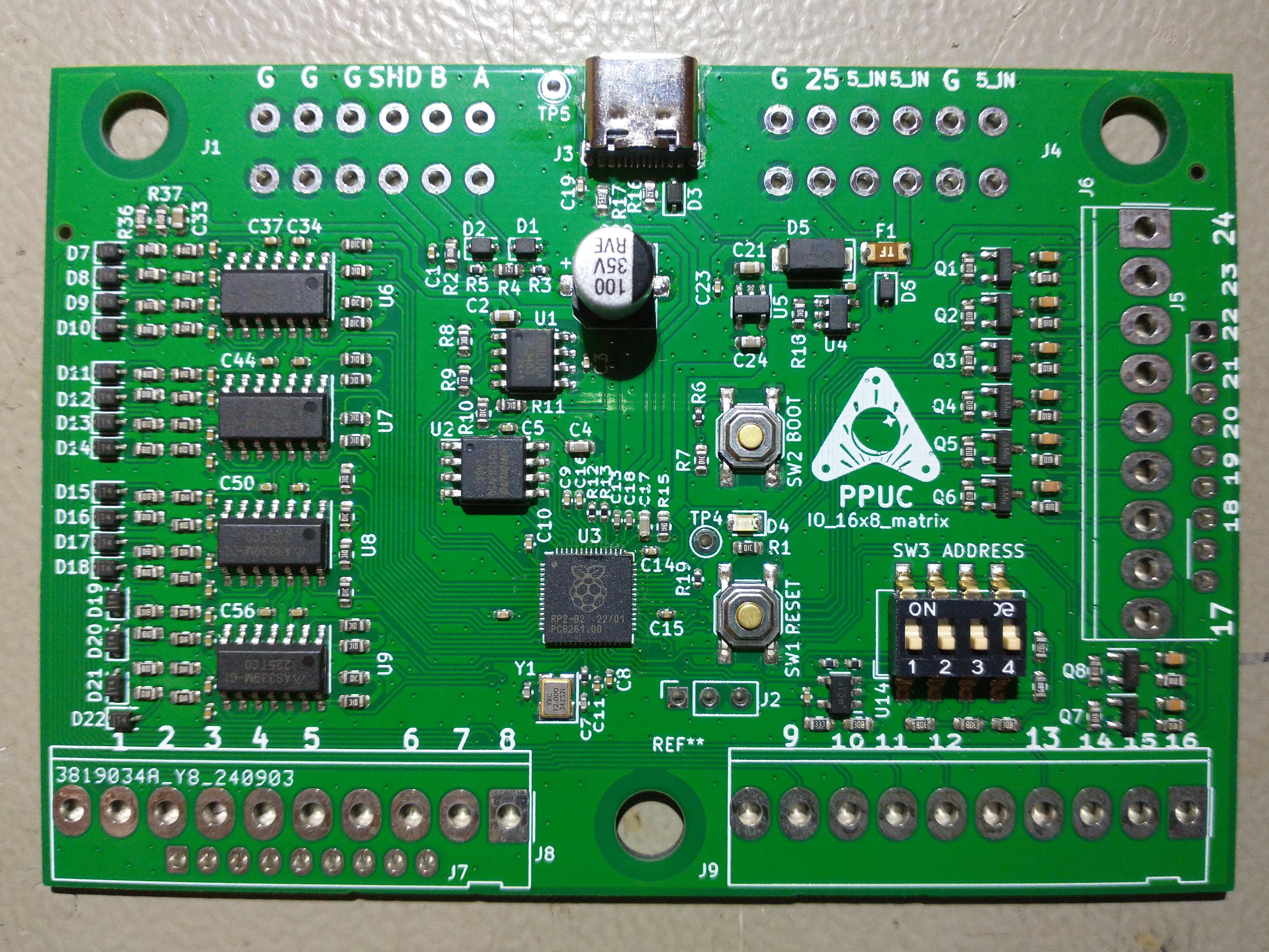
IO_16x8_matrix as it has 16 inputs and 8 signal-outputs to form a 16x8 switch matrix but could also be used as direct inputs and low power outputs. Actually it has an additional high speed output (see "Special Output" below).
The IO card must be supplied by 5 V (+-0.5 V). In the circuit this is named 5V_IN.
A RP2040 is used for it's cost/performance ratio. It is the same controller that is used in the Raspberry Pi Pico.
There are 8 outputs that can be set to 5 V or GND. They are intended to drive the switch matrix (column at WPC, row at S.A.M.). The 5 V signal is derived from the 5 V supply by a 1 kOhm pull up resistor. Therefore it is only good for signaling, not for power load. If used as a matrix please be aware that every switch must have a diode in series.
There are 16 inputs intended to receive the switch status of the matrix (row at WPC, column at S.A.M.). They are pulled up to 5 V and switch at a voltage of about 1.9 V. The inputs are made for low active signals (switched to GND). If used as a matrix please be aware that every switch must have a diode in series.
One special output is available for high speed signals. The voltage is 5 V, it is a push pull output that can drive a current up to 8 mA. It can be used to e.g. control a WS2812 LED strip.
There are pads for connectors that fit S.A.M. systems and also WPC systems. The pinning of the returns (rows at WPC) is unfortunately vice versa to S.A.M. so the connector of the original WPC cable harness has to be rotated by 180° (cables go to the inner side of PCB).
| Qty | Value | Footprint | References |
|---|---|---|---|
| 39 | 100n | Capacitor_SMD:C_0402_1005Metric | C1, C3, C10, C11, C12, C14, C15, C16, C19, C20, C23, C34, C35, C36, C37, C38 +23 |
| 32 | 1k | Resistor_SMD:R_0603_1608Metric | R20, R21, R22, R23, R24, R25, R26, R27, R28, R29, R30, R31, R32, R33, R34, R35 +16 |
| 22 | 10k | Resistor_SMD:R_0603_1608Metric | R1, R7, R10, R11, R18, R38, R39, R44, R45, R50, R51, R65, R66, R71, R72, R77 +6 |
| 18 | 100R | Resistor_SMD:R_0603_1608Metric | R2, R15, R40, R41, R46, R47, R52, R53, R67, R68, R73, R74, R79, R80, R85, R86 +2 |
| 16 | 1N4148WS | Diode_SMD:D_SOD-323 | D7, D8, D9, D10, D11, D12, D13, D14, D15, D16, D17, D18, D19, D20, D21, D22 |
| 8 | 10n | Capacitor_SMD:C_0603_1608Metric | C25, C26, C27, C28, C29, C30, C31, C32 |
| 8 | MMBT3904 | Package_TO_SOT_SMD:SOT-23 | Q1, Q2, Q3, Q4, Q5, Q6, Q7, Q8 |
| 6 | 10u | Capacitor_SMD:C_0603_1608Metric | C2, C4, C17, C21, C24, C33 |
| 6 | 2k | Resistor_SMD:R_0603_1608Metric | R36, R37, R57, R60, R61, R64 |
| 5 | 1k | Resistor_SMD:R_0402_1005Metric | R6, R14, R19, R58, R62 |
| 4 | LM339 | Package_SO:SOIC-14_3.9x8.7mm_P1.27mm | U6, U7, U8, U9 |
| 2 | 1A | Diode_SMD:D_SOD-323 | D3, D23 |
| 2 | 1u | Capacitor_SMD:C_0402_1005Metric | C13, C18 |
| 2 | 27 | Resistor_SMD:R_0402_1005Metric | R12, R13 |
| 2 | 27pF | Capacitor_SMD:C_0402_1005Metric | C6, C7 |
| 2 | 5k1 | Resistor_SMD:R_0603_1608Metric | R16, R17 |
| 2 | Conn_01x06 | Out_8x10:Terminal_Block_RTMPin | J1, J4 |
| 2 | Conn_01x09 | Connector_Molex:Molex_KK-254_AE-6410-09A_1x09_P2.54mm_Vertical | J5, J7 |
| 2 | Conn_01x10 | Connector_Molex:Molex_KK-396_5273-10A_1x10_P3.96mm_Vertical | J8, J9 |
| 2 | SD15 | Diode_SMD:D_SOD-323 | D1, D2 |
| 1 | 0 | Resistor_SMD:R_0603_1608Metric | R9 |
| 1 | 100µ 35V | Capacitor_SMD:CP_Elec_6.3x7.7 | C22 |
| 1 | 120R | Resistor_SMD:R_0603_1608Metric | R4 |
| 1 | 12MHz,18pF | Crystal:Crystal_SMD_3225-4Pin_3.2x2.5mm | Y1 |
| 1 | 33k | Resistor_SMD:R_0603_1608Metric | R56 |
| 1 | 3k | Resistor_SMD:R_0603_1608Metric | R63 |
| 1 | 5k | Resistor_SMD:R_0603_1608Metric | R59 |
| 1 | ADDRESS | Button_Switch_SMD:SW_DIP_SPSTx04_Slide_6.7x11.72mm_W8.61mm_P2.54mm_LowProfile | SW3 |
| 1 | ADM3483 | Package_SO:SOIC-8_3.9x4.9mm_P1.27mm | U1 |
| 1 | AP2112K-3.3 | Package_TO_SOT_SMD:SOT-23-5 | U5 |
| 1 | Boot | Button_Switch_SMD:SW_SPST_SKQG_WithStem | SW2 |
| 1 | Conn_01x09 | Connector_Molex:Molex_KK-396_5273-09A_1x09_P3.96mm_Vertical | J6 |
| 1 | Jumper_2_Open | Connector_PinHeader_2.54mm:PinHeader_1x02_P2.54mm_Vertical | JP1 |
| 1 | LED gn | LED_SMD:LED_0805_2012Metric | D4 |
| 1 | LMV321 | Package_TO_SOT_SMD:SOT-23-5 | U14 |
| 1 | RP2040 | Package_DFN_QFN:QFN-56-1EP_7x7mm_P0.4mm_EP3.2x3.2mm | U3 |
| 1 | Reset | Button_Switch_SMD:SW_SPST_SKQG_WithStem | SW1 |
| 1 | SD05 | Diode_SMD:D_SOD-323 | D6 |
| 1 | SMAJ5.0 | Diode_SMD:D_SMA | D5 |
| 1 | SN74AHCT1G125 | Package_TO_SOT_SMD:SOT-23-5 | U4 |
| 1 | TP_GND | Connector_Pin:Pin_D1.0mm_L10.0mm | TP5 |
| 1 | TP_LED | Connector_Pin:Pin_D1.0mm_L10.0mm | TP4 |
| 1 | USB_C_Receptacle_USB2.0 | Connector_USB:USB_C_Receptacle_XKB_U262-16XN-4BVC11 | J3 |
| 1 | W25Q128JVSIQ | Package_SO:SOIC-8_5.23x5.23mm_P1.27mm | U2 |
| 1 | nmount SW Debug | Connector_PinSocket_2.54mm:PinSocket_1x03_P2.54mm_Vertical | J2 |
The 207 most common of 210 parts.


Filip-Kin/frc-radio-kiosk
Bench box that powers and configures FRC radios: dual-mode PoE (802.3at via LTC4279, passive 12 V via TPS26600), USB-C PD or DC in, 15.6 V out for the Toughbook, 4x CR123A backup, STM32F072 firmware.

DangerousPrototypes/BusPirate5-hardware
Bus Pirate Hardware and accessories for v5 and higher

hspil/greenhouse-controller-pcb
Central controller for greenhouse automation project

Rustaphor/LightRelay4Camping
Analog light sensor to night power up LED garland. For Camping use.

dennowiggle/FLEADiP
FLEADiP is a compatiable add-on board for the Z80 Retro! project
It measures 97.6 × 67.3 mm and has 2 copper layers, 1.6 mm thick.
210 parts, built around the RP2040, ADM3483ARZ, SN74AHCT1G125DBV and LMV321. The full list of its parts is on this page, with links to each part's symbol and footprint where PCBKit's library has them.
From the PPUC/Hardware_IO_16x8_matrix repository on GitHub, at the commit this page was made from: the board is IO_16x8_matrix/IO_16x8_matrix.kicad_pcb and its schematic IO_16x8_matrix/Drv8.kicad_sch. PCBKit opens the board in the browser, with nothing to install.
Its repository states no licence, so its author keeps all rights: ask PPUC before reusing the design.