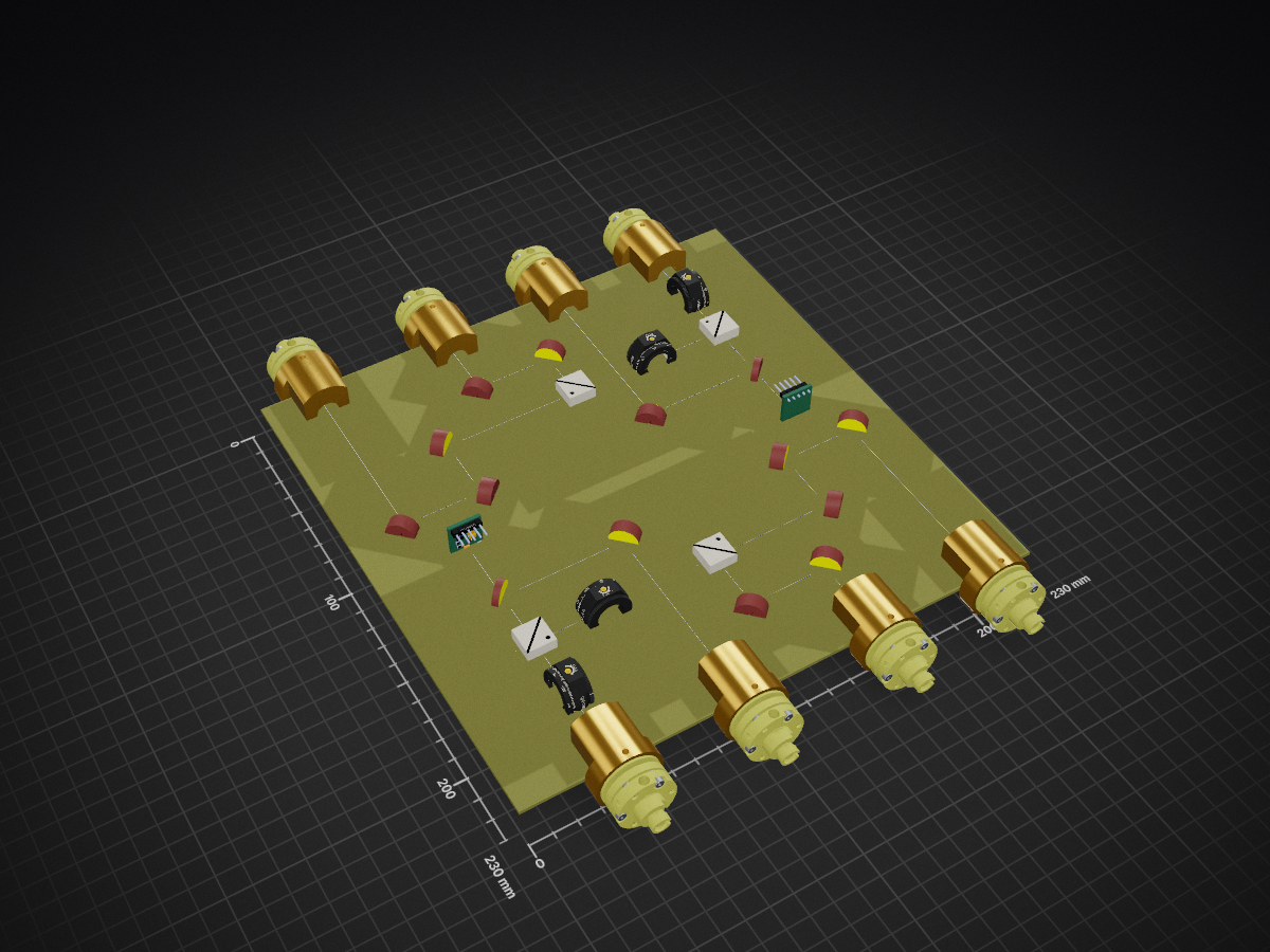
2 layers230 × 230 mm
20250110-679disV01
OpticsFoundry/Kicad-Library-Optics
Library for designing optical setups in KiCad. These designs can be imported into the optical circuit board manufacturing system of OpticsFoudnry.
17 parts7MIT
 OpticsFoundry/Kicad-Library-Optics7
Library for designing optical setups in KiCad. These designs can be imported into the optical circuit board manufacturing system of OpticsFoudnry.
20250110-679and707disV01 is an open-source printed circuit board by OpticsFoundry, from the OpticsFoundry/Kicad-Library-Optics repository on GitHub, published under the MIT licence. It is a 2-layer board of 230 × 230 mm with 33 parts on 34 nets, routed with 45 tracks and 4 vias.
Its parts include 8 capacitors and 2 diodes.
This repository includes a library for designing optical setups in KiCad.
Please visit our website for more product and ordering.
If you have any question or need help, write to us: opticsfoundry@gmail.com
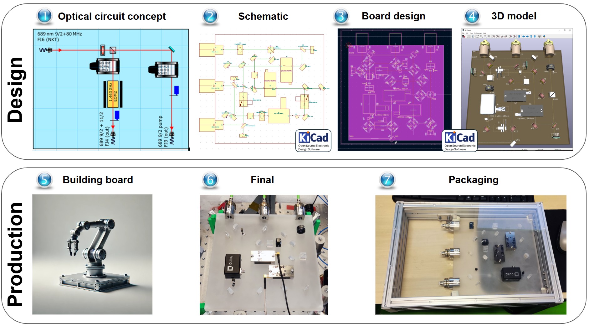
KiCad is an open source electronic design software. However, we have developed this library to be able to design optical setup. The procedure of producing an optical setup with Robot developed by OpticsFoundry is shown below.
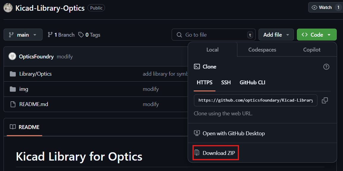
Preferences tab, click on Configure Paths... as shown below,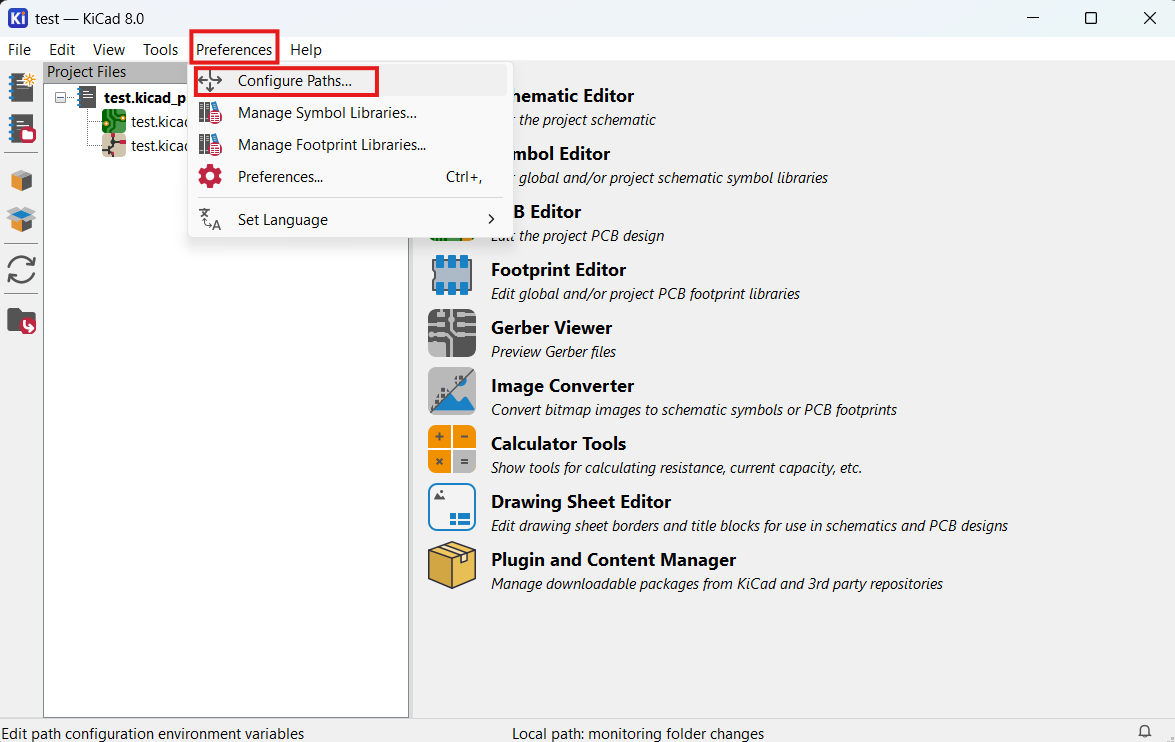
KIGITHUB with path https://github.com/KiCad. As shown below,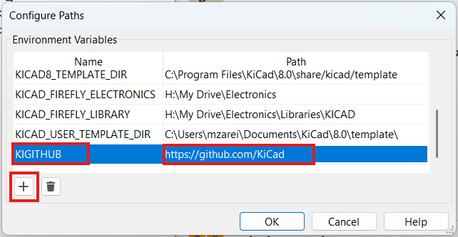
KICAD_FIREFLY_OPTICS, for the path click on folder icon and go to the path which the library has been downloaded then select Optics folder. As shown in following pictures,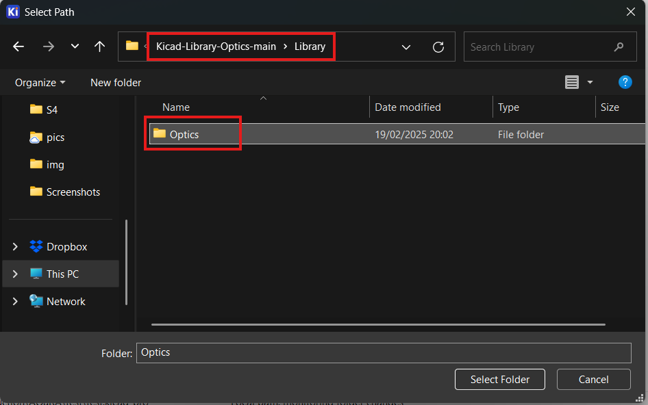
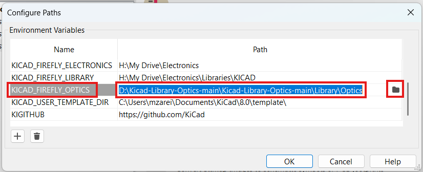
OK and close the window,Preferences tab, click on Manage Symbol Libraries...,Optics with library path ${KICAD_FIREFLY_OPTICS}/Symbols/Optics.kicad_sym. As shown below,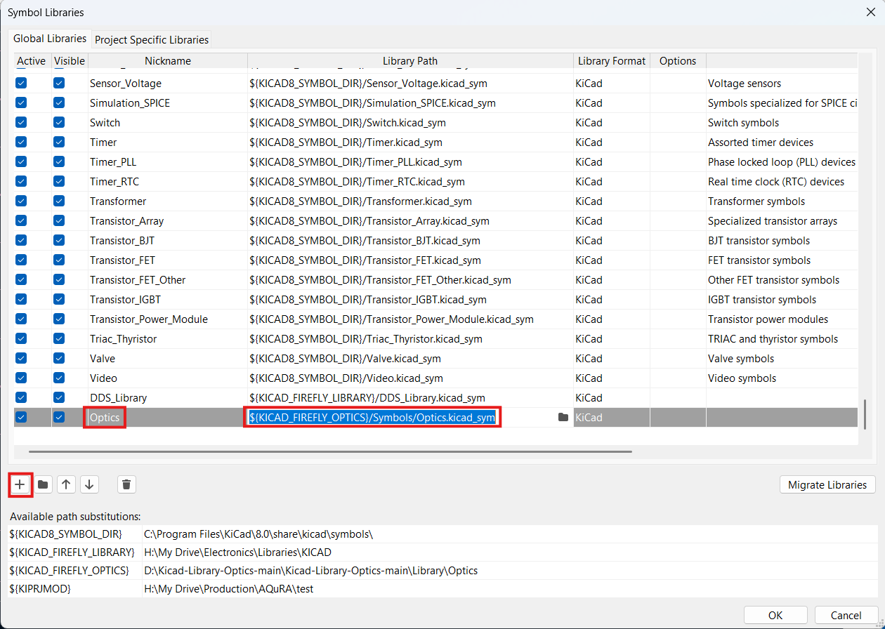
OK and close the window. If you encounter an error like below, probably the path is not defined correctly,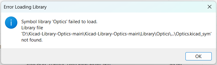
Preferences tab, click on Manage Footprint Libraries...,Optics with library path ${KICAD_FIREFLY_OPTICS}/Footprints/Optics.pretty, at the end click on OK and close the window. As shown below,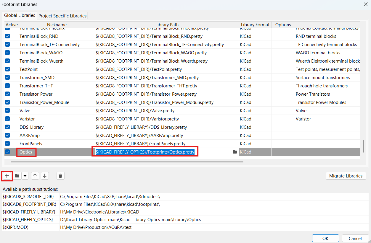
Symbol Editor and Footprint Editor in Tools tab. As shown below,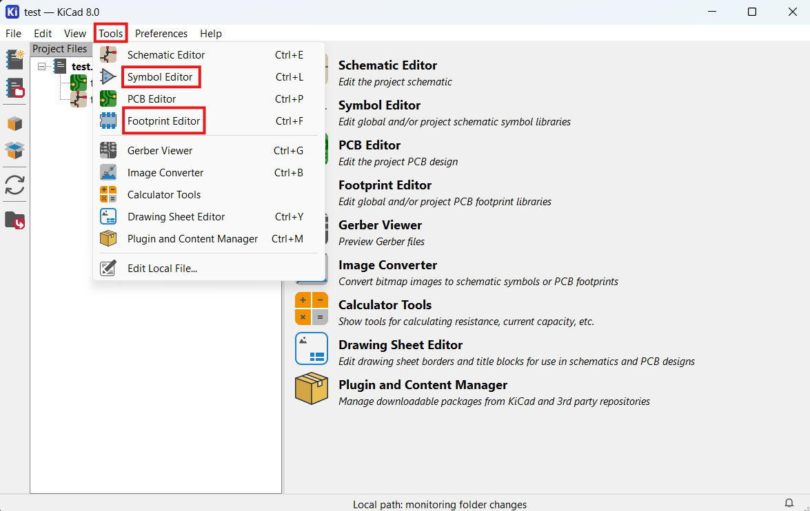
Optics library in search bar, you should be able to see list of all the optical symbols and footprint. As shown in following pictures,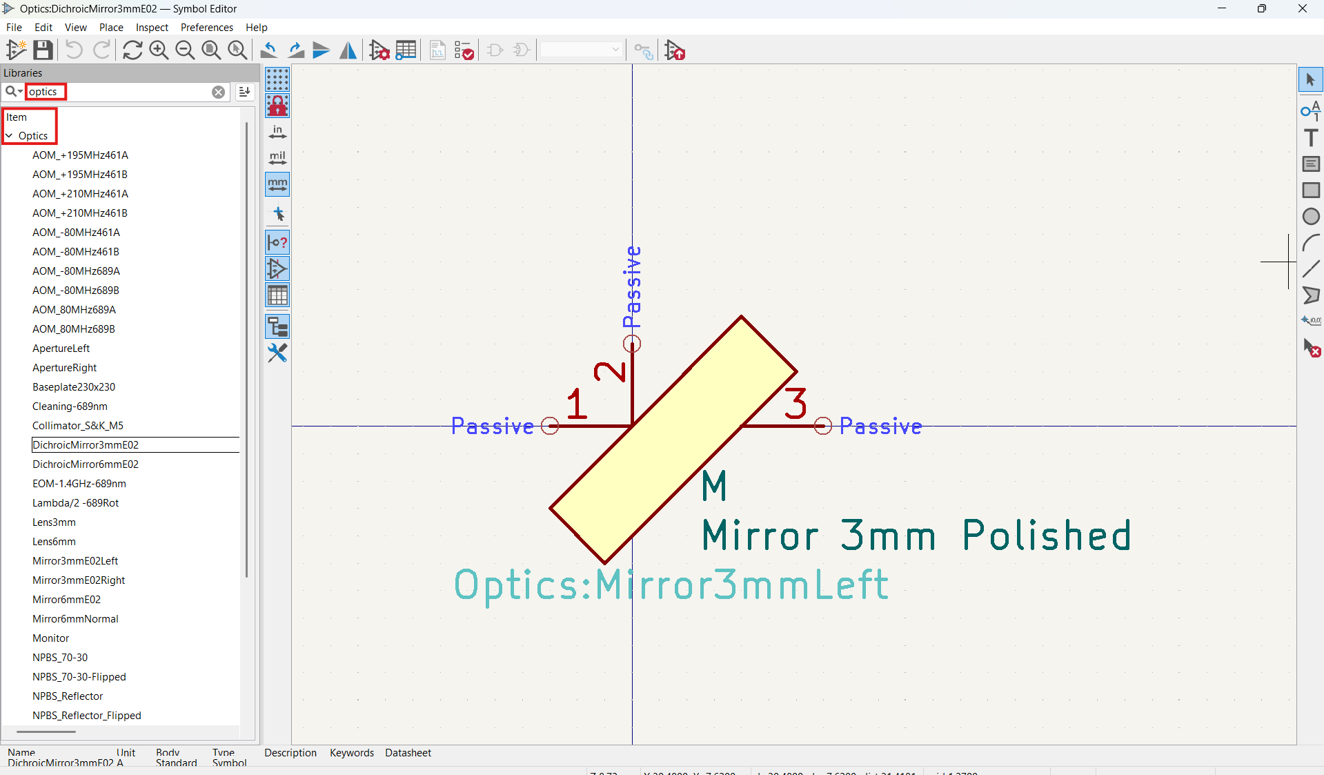
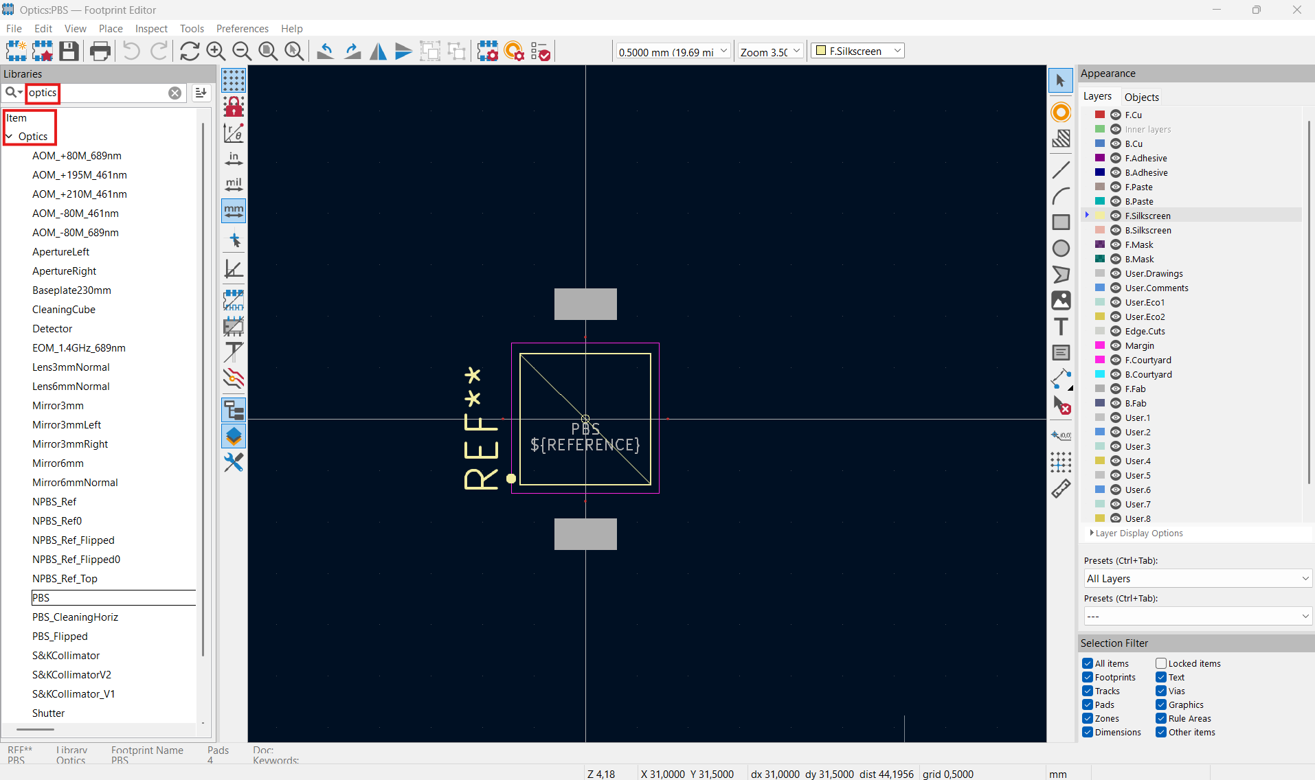
Now you can start a new project and open schematic editor to design your optical setup, as shown below.
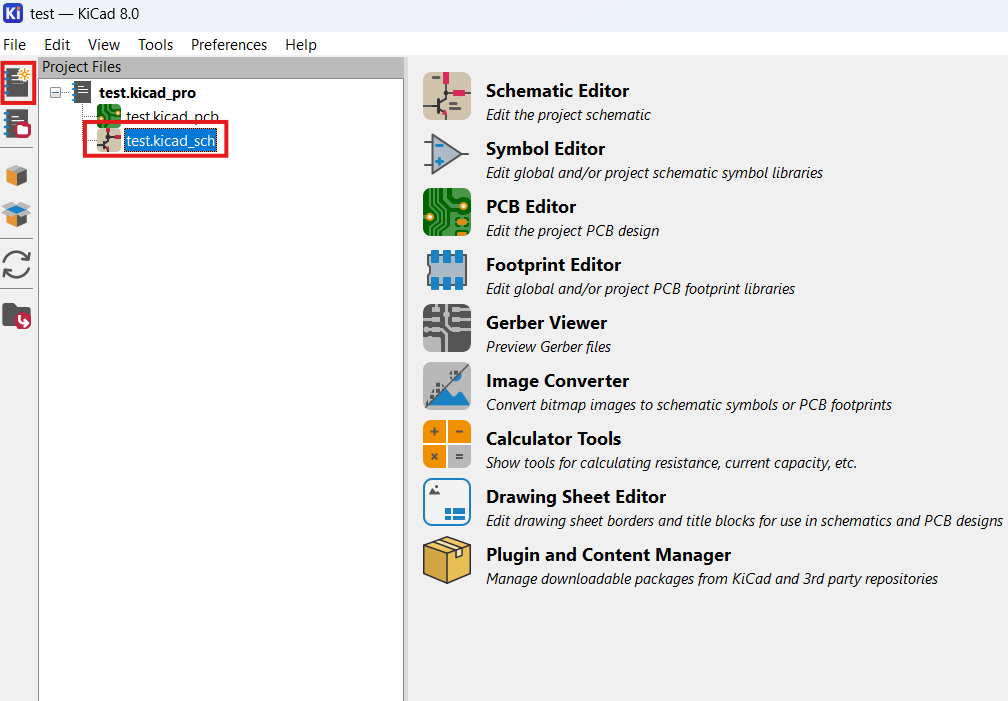
You could also copy one of the examples or use one of the Free Projects for starting point.
Note Standard optics hight is 7.5 mm, if optics hight of your components is smaller or bigger, please write to us: opticsfoundry@gmail.com
Note If you need a specific baseplate size or any other components which are not available in Symbols, please write to us: opticsfoundry@gmail.com
Based on your design, you need to choose baseplate size for your board.
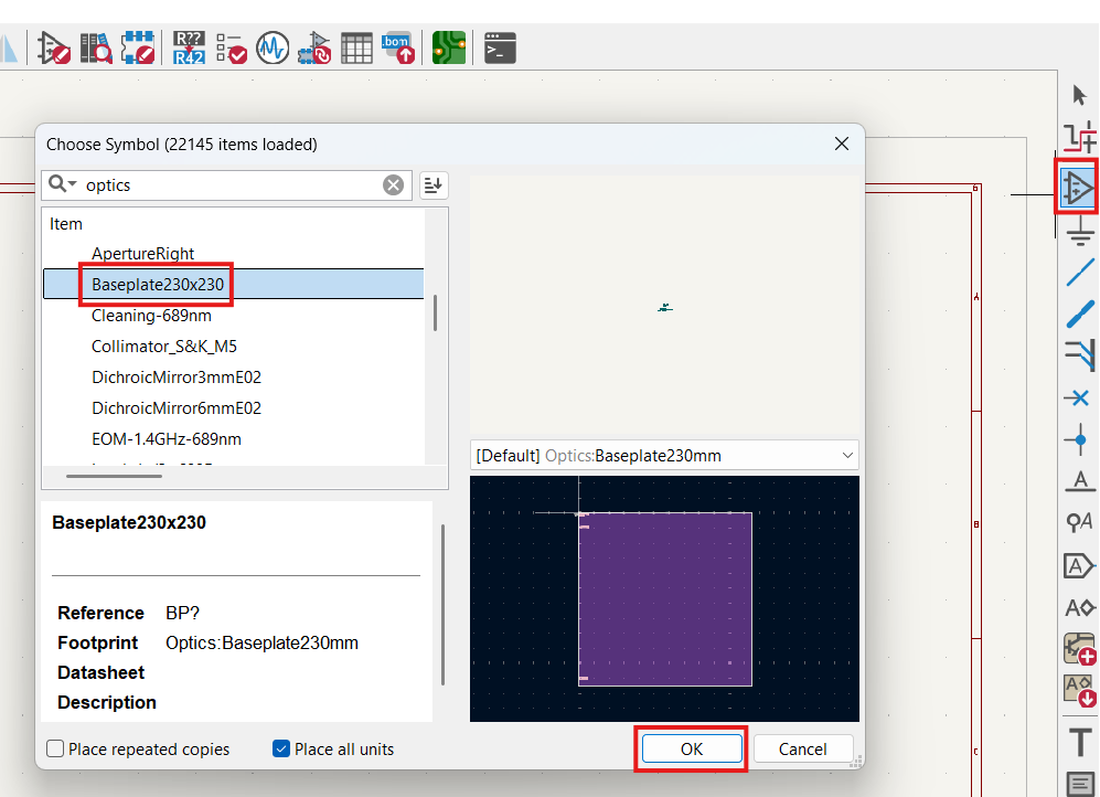
If your page size is smaller than baseplate, you can change it in the page settings from File tab for schematic and footprint editors.
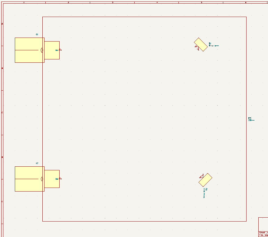
Schematic editor looks like this after adding baseplate.
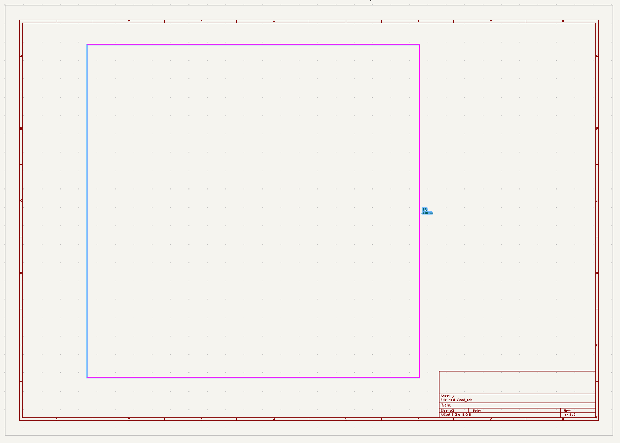
I have added two collimators and mirrors to design a fiber to fiber setup.
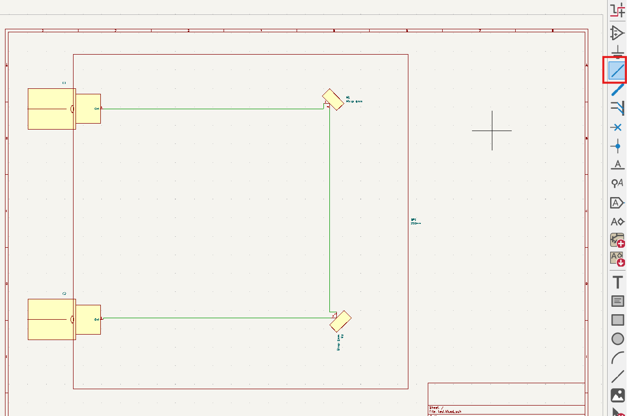
By selecting wire, you can draw the beam path.
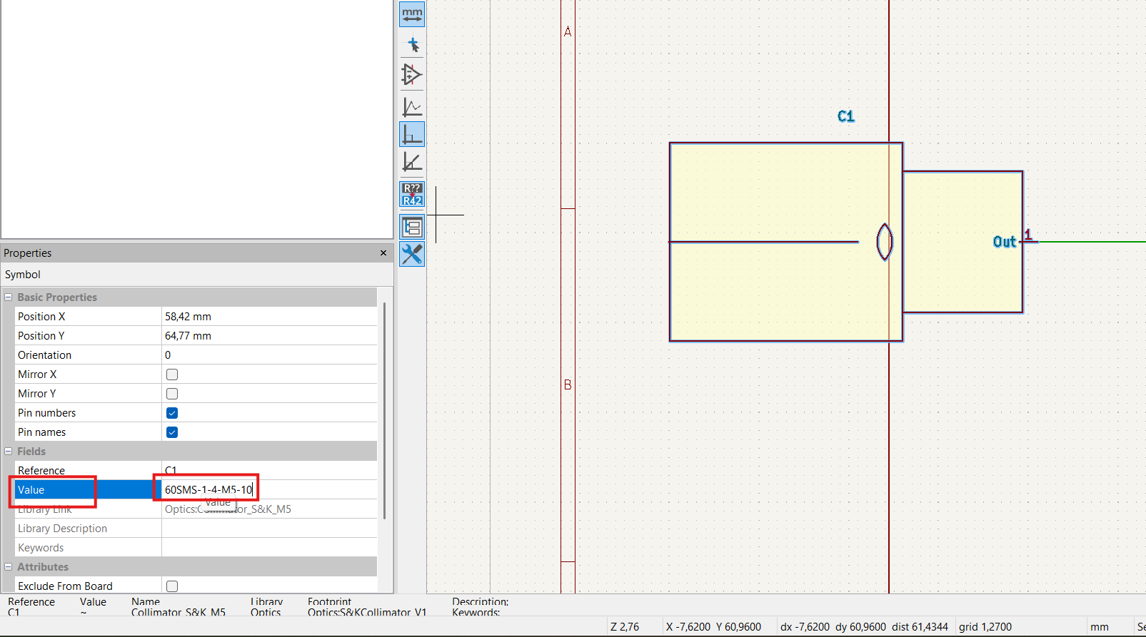
Each component need to be defined by selecting the component and changing the value based on what is your need.
After finishing your design, save all changes in schematic editor. NOw you could move to PCB editor and update your PCB from Schematic.
Note You could also update PCB design each time after adding any new components.
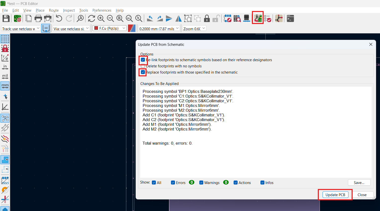
Click on Update PCB from Schematic... in PCB editor, then update PCB and close the window as shown below.
Now the PCB looks like this:
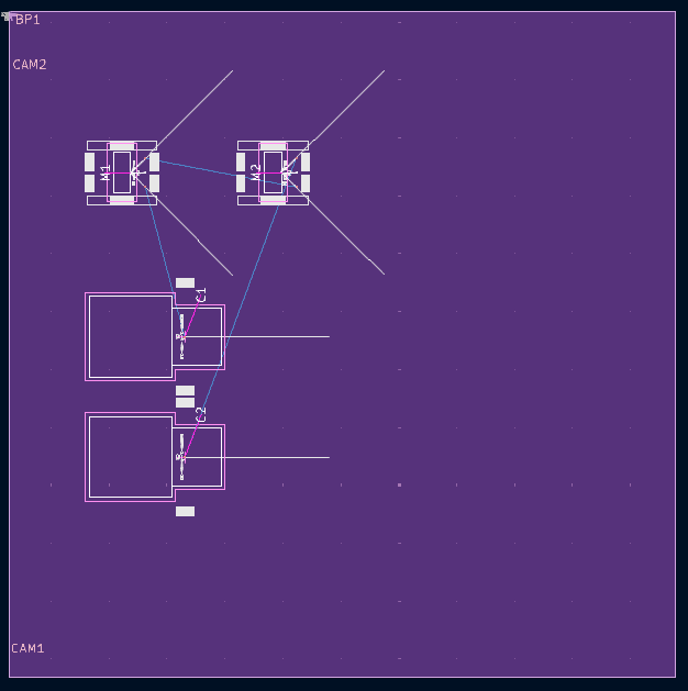
Each component need to be selected and reposition and rerotate based on reality.
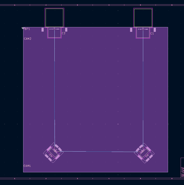
This example is available in test
| Qty | Value | Footprint | References |
|---|---|---|---|
| 12 | Mirror 6mm | Optics:Mirror6mm | M1, M3, M4, M5, M6, M7, M8, M9, M10, M12, M13, M14 |
| 4 | 689nm 11/2 Out, 60SMS-1-4-A4.5S-02 | Optics:S&KCollimator_V1 | C2, C4, C6, C7 |
| 4 | L/2@689nm - Rotatable | Optics:WaveplateRotateable | WPR1, WPR2, WPR3, WPR4 |
| 2 | 689nm 9/2 Out, 60SMS-1-4-A4.5S-02 | Optics:S&KCollimator_V1 | C1, C8 |
| 2 | 689nm Source, 60SMS-1-4-M5-10 | Optics:S&KCollimator_V1 | C3, C5 |
| 2 | Mirror 3mm Polished | Optics:Mirror3mmRight | M2, M11 |
| 2 | Monitor | Optics:Detector | D1, D2 |
| 2 | NPBS-70:30-Flipped | Optics:PBS_Flipped | NPBSF1, NPBSF3 |
| 2 | PBSCasix689nm | Optics:PBS | PBS1, PBS2 |
| 1 | 230mm | Optics:Baseplate230mm | BP1 |
OpticsFoundry/Kicad-Library-Optics
Library for designing optical setups in KiCad. These designs can be imported into the optical circuit board manufacturing system of OpticsFoudnry.

hoglet67/RGBtoHDMI
Bare-metal Raspberry Pi project that provides pixel-perfect sampling of Retro Computer RGB/YUV video and conversion to HDMI

mntmn/amiga2000-gfxcard
MNT VA2000, an Open Source Amiga 2/3/4000 Graphics Card (Zorro II/III), written in Verilog

hackclub/OnBoard
💡 Join 1,000 teenagers and make your first PCB with a $100 grant!

Arrow-air/project-quiver
Project Quiver documentation, designs, and project artifacts.

ozel/DIY_particle_detector
A mobile low-cost spectrometer for measuring radioactivity and the energy of ionising radiation like alpha particles and electrons

BlueAndi/Pixelix
Full RGB LED matrix, based on an ESP32 and WS2812B LEDs or emulated LEDs on TFT.

jrsteensen/OpenHornet
OpenHornet 1:1 F/A-18C Simulator Repository

It measures 230 × 230 mm and has 2 copper layers, 1.6 mm thick.
33 parts. The full list of its parts is on this page, with links to each part's symbol and footprint where PCBKit's library has them.
From the OpticsFoundry/Kicad-Library-Optics repository on GitHub, at the commit this page was made from: the board is Examples/20250110-LabUse-679and707dis/20250110-679and707disV01.kicad_pcb and its schematic Examples/20250110-LabUse-679and707dis/20250110-679and707disV01.kicad_sch. PCBKit opens the board in the browser, with nothing to install.
Its repository publishes it under the MIT licence: you may reuse it on that licence's terms (keep the author's notice, and for a copyleft licence share your changes alike).