Skip to the content
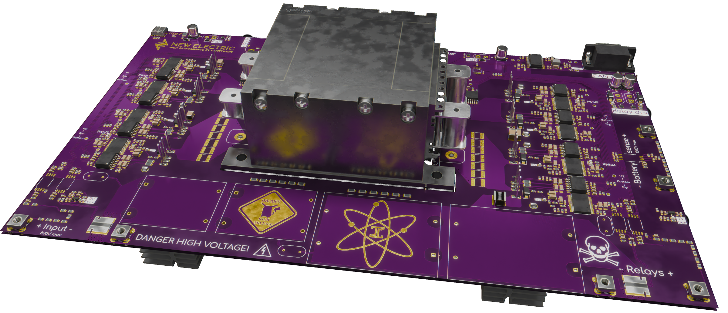
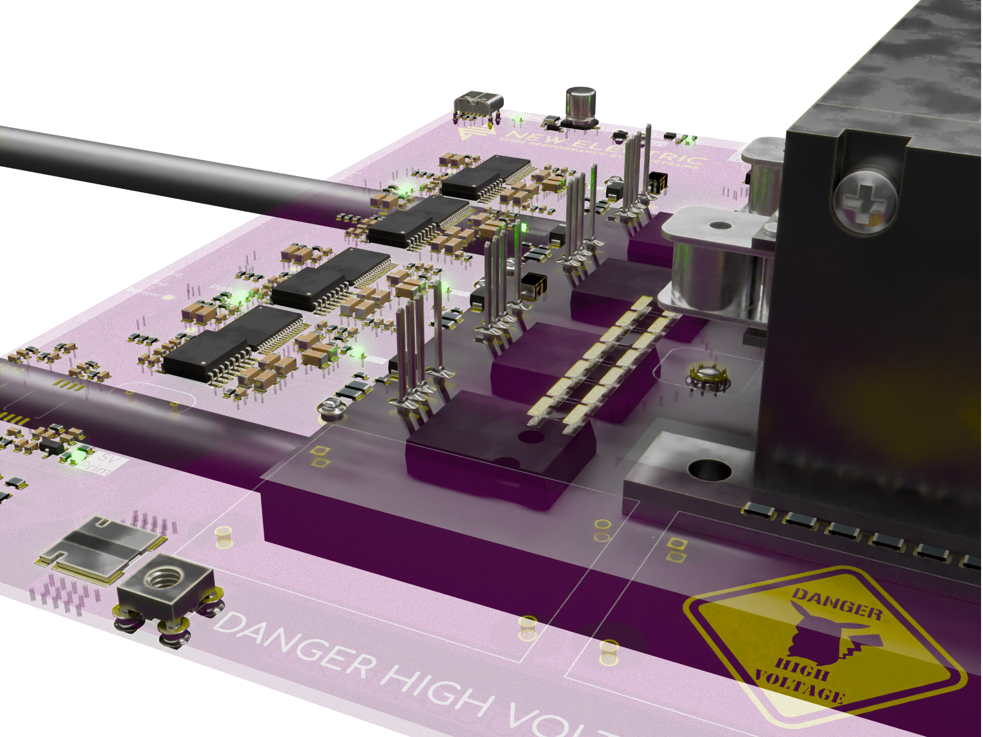
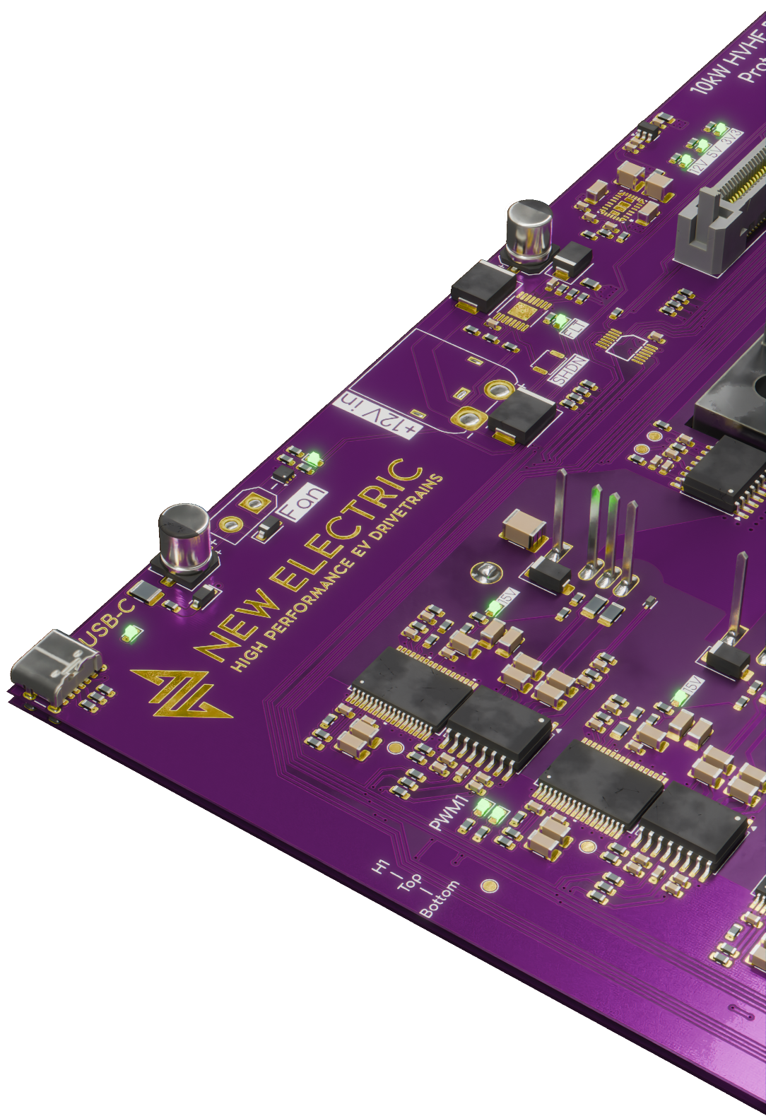
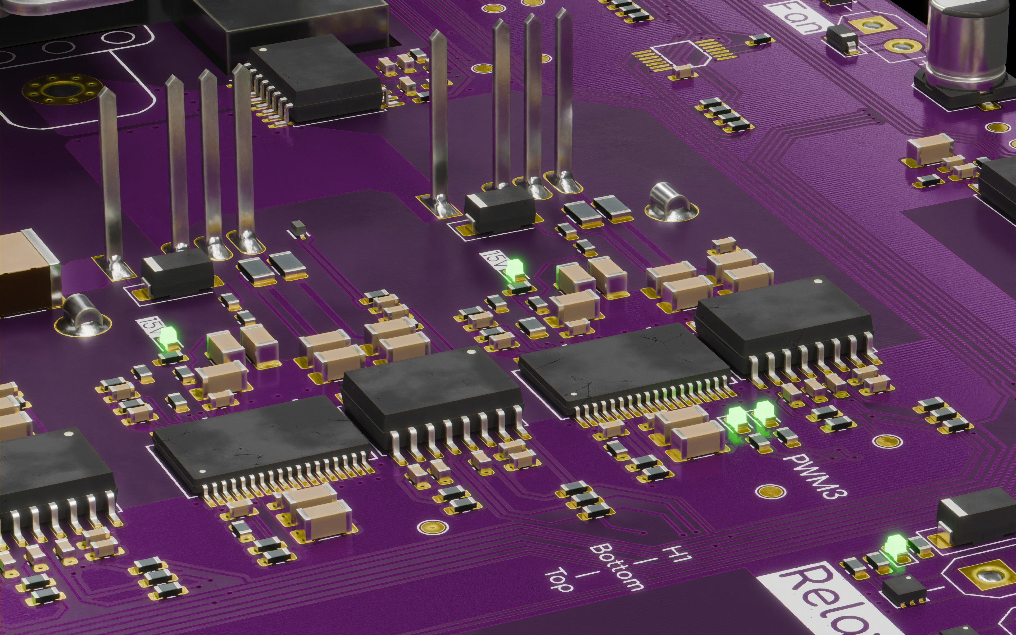
6 layers320.6 × 186.1 mmDAB, the printed circuit board in 3D

a 10kW 800V to 200-1000VDC DAB DCDC converter

Size
320.6 × 186.1 mm
Copper layers
6
Thickness
1.81 mm
Parts
761
Nets
461
Pads
2,320
Tracks, vias
3,275, 1,545
Pours
115
Routed
Yes
KiCad
KiCad 8.0 (file 20240108)
Created
4 Jul 2026
Updated
4 Jul 2026

Overview

DAB is an open-source printed circuit board by NovaPrime18, from the NovaPrime18/DAB_DCDC repository on GitHub, published under the CERN-OHL-S-2.0 licence. It is a 6-layer board of 320.6 × 186.1 mm with 761 parts on 461 nets, routed with 3,275 tracks and 1,545 vias.

It is built around the UCC14141QDWNRQ1, SN74LVC126APWR-TP and UCC21710QDWQ1, with the AMC1306M05DWVR, AMC1336DWVR and 150060VS75000 among its other parts. Its parts include 301 capacitors, 279 resistors, 42 diodes, 26 ICs and 12 transistors. It belongs with the power boards of this library.

Main components

12

README

README.md

10kW Dual Active Bridge DC-DC Converter

License: CERN-OHL-S v2.0 KiCad

Hardware files for a high-power, high-frequency DC-DC converter PCB, developed as a prototype module for a modular 500kW off-grid EV DC fast charger. The board implements a Dual Active Bridge (DAB) topology with a planar transformer, isolated gate drivers and sensing, and on-board water/air cooling provisions for the power stage.

This board is a single prototype module. Multiple modules are intended to be run in parallel and/or series to scale up to the full 500kW system.


Key specifications

ParameterValue
TopologyDual Active Bridge (DAB)
Input voltage500–800V DC
Output voltage250–1000V DC (peak efficiency at 666V)
Output power~10kW per module
Output currentPrimary 15A (22A peak), Secondary 17A (25A peak)
Switching frequency100kHz
IsolationGalvanic, via transformer (10,000V dielectric strength primary/secondary)
TransformerPayton Planar, 24:20 turns ratio, 35µH total leakage inductance
ControlTI controlCARD via CAN bus, phase-shift power regulation
PCB6 layers, 70µm (2oz) copper, 2mm FR4
Secondary switchesMicrochip MSC035SMA170B4 SiC MOSFETs (1700V)
Clearance / creepage3mm (primary) / 3.5mm (secondary), per IPC-2221 / IEC-60664
Voltage derating1.7x on HV secondary components
CoolingFin-stack air-cooled heatsinks or aluminum liquid-cooling plate (SiCFETs + transformer)
ConnectorsXT30 for HV in/out (contactors are off-board)

Board design notes

  • All components are placed on the top side only for simpler, cheaper assembly; the transformer sits in the middle and physically supports the board (and the cooling plate, when fitted).
  • Six copper layers at 70µm are used (instead of the reference design's 4 layers) to reduce conduction losses at higher secondary currents.
  • HV secondary components are rated to 1700V to handle voltage spikes at the 1000V output target, with 1.7x derating.
  • DC blocking capacitors are 2280-package, 1700V rated, double-stacked to reach the required capacitance. A future revision should move to the 3640 package, which has more capacitance per area but does not fit the current footprint.
  • Contactors are not on the PCB — HV switching is handled externally via XT30 connectors, allowing higher-voltage contactors to be selected independently of the board.
  • Isolated 5V and gate-drive supplies are derived on-board; see "Known issues" below for a wiring correction needed for the secondary-side isolated 5V rail.
  • Designed and manufactured through JLCPCB (6-layer, double-thick copper, 2mm FR4).

Design rule summary

These rules were applied during layout and should be followed in any revision:

  • High current: ~1 via per amp for stitching/heat spreading, no 90° corner traces, 70µm copper minimum, 6-layer stack-up. Trace rise kept to ≤10°C above ambient at 30A (verified with KiCad's trace-width calculator).
  • High frequency: Ferrite-core planar transformer, short/direct high-frequency traces, minimized loop areas to limit EMI and parasitic inductance.
  • High voltage: Clearance/creepage per IPC-2221 and IEC-60664 (3.5mm creepage at 1000V), 2x voltage derating where practical, Plastik 70 conformal coating (>85kV/mm dielectric strength) on the assembled board.
  • Thermal: Copper-filled vias, water-cooled or finned aluminum heatsinks on SiCFETs and transformer core.
## Known issues / errata (first prototype build)

These were found during assembly/bring-up of the first board and are not yet fixed on this design unless noted — see schematics for full details:

  • eFuse (TPS26400): Pins 3 and 5 were swapped in the footprint, preventing power-up. Fixed on the physical board with bodge wires; needs a schematic/footprint fix in the next revision.
  • controlCARD connector: The standard KiCad/Digikey footprint for TI's connector has reversed pin numbering vs. TI's own controlCARD. A separate flip-adapter PCB is required as a workaround (included in this repo). The adapter should be ordered in 1mm board thickness, not 1.7mm, to avoid breaking the socket pins on connector insertion.
  • Isolated PSU current limit (Rlim): Original 1k current-limit resistor caused overcurrent-protection faults on startup due to 5V rail capacitance. Change to 270R.
  • Primary-side sensing pinout: DS modulator interface pins to the controlCARD were routed to pins that don't support DS modulators; rerouted with magnet wire on the prototype and needs correcting in the footprint/routing.
  • Secondary isolated 5V supply: Originally derived from the "top" isolated supply of H2, whose ground floats to 1000V half the switching cycle. Must be re-derived from the "bottom" isolated supply of H2 instead.
  • Cooling clearance: Backside DC capacitors interfere with the aluminum cooling plate; stack capacitors on the top side instead. The transformer cutout also needs enlarging — it's currently a tight fit.

⚠️ Due to the eFuse/pinout bodges above, this specific assembled prototype should only be tested at low voltage (LV), not at its rated HV, until a corrected revision is built.

Repository contents

  • Schematics and PCB layout (KiCad)
  • Fabrication outputs (Gerbers / stencil) as ordered from JLCPCB
  • controlCARD adapter PCB (flips connector pinout, 90° mount)
  • Renders of the assembled board and cooling solutions

Background

This board was developed as part of an internship thesis evaluating the feasibility of in-house production of a 500kW off-grid EV DC fast charger, based on and enhanced from a Texas Instruments DAB reference design. Full design rationale, simulation results (LTspice/PLECS), and test results are documented in the accompanying thesis — this README covers only the PCB/hardware side.

Parts

761
QtyValueFootprintReferences
59100nFCapacitor_SMD:C_0603_1608MetricC102, C106, C109, C110, C111, C113, C127, C130, C131, C133, C147, C150, C151, C152, C154, C168 +43
4610kResistor_SMD:R_0603_1608MetricR15, R16, R103, R118, R122, R138, R142, R157, R160, R161, R162, R163, R164, R165, R166, R167 +30
280.47uCapacitor_SMD:C_2220_5750MetricC10, C11, C12, C13, C14, C15, C16, C17, C18, C19, C20, C24, C25, C26, C27, C28 +12
26100Resistor_SMD:R_0603_1608MetricR100, R101, R102, R119, R120, R121, R139, R140, R141, R169, R170, R171, R189, R190, R191, R232 +10
26150060VS75000LED_SMD:LED_0603_1608MetricD11, D13, D15, D17, D19, D21, D22, D23, D27, D31, D32, D33, D34, D35, D36, D37 +10
24100nFCapacitor_SMD:C_1206_3216MetricC112, C116, C117, C132, C136, C137, C153, C157, C158, C173, C177, C178, C195, C199, C200, C215 +8
24100pFCapacitor_SMD:C_0603_1608MetricC104, C105, C107, C125, C126, C128, C145, C146, C148, C166, C167, C169, C187, C188, C190, C208 +8
24330pFCapacitor_SMD:C_0603_1608MetricC101, C118, C121, C122, C138, C141, C142, C159, C162, C163, C179, C182, C183, C201, C204, C205 +8
24634kResistor_SMD:R_0805_2012MetricR19, R20, R21, R22, R23, R24, R220, R221, R222, R226, R227, R228, R229, R230, R240, R241 +8
2110uFCapacitor_SMD:C_1206_3216MetricC103, C123, C124, C143, C144, C164, C165, C185, C186, C206, C207, C271, C272, C279, C281, C286 +5
190Resistor_SMD:R_0603_1608MetricR28, R49, R50, R62, R105, R106, R124, R125, R144, R145, R174, R175, R194, R195, R231, R252 +3
1926R @ 100MHz 6.5AResistor_SMD:R_0603_1608MetricFB1, FB2, FB3, FB4, FB5, FB6, FB10, FB11, FB12, FB13, FB14, FB15, FB16, FB17, FB18, FB19 +3
181uFCapacitor_SMD:C_0603_1608MetricC108, C129, C149, C170, C191, C212, C229, C234, C237, C258, C259, C263, C273, C277, C282, C285 +2
162Resistor_SMD:R_1206_3216MetricR56, R57, R64, R65, R88, R89, R108, R109, R127, R128, R147, R148, R177, R178, R197, R198
15220Resistor_SMD:R_0603_1608MetricR159, R223, R224, R225, R235, R257, R263, R264, R272, R277, R295, R296, R297, R298, R299
142.2uFCapacitor_SMD:C_0603_1608MetricC53, C55, C228, C232, C240, C242, C247, C248, C253, C254, C264, C265, C304, C308
13100kResistor_SMD:R_0603_1608MetricR32, R41, R87, R107, R126, R146, R176, R196, R236, R258, R270, R303, R306
121MResistor_SMD:R_1206_3216MetricR2, R3, R4, R5, R6, R7, R8, R9, R10, R11, R12, R13
1110pFCapacitor_SMD:C_0603_1608MetricC57, C58, C59, C233, C241, C255, C256, C297, C298, C299, C300
910nFCapacitor_SMD:C_0603_1608MetricC278, C283, C284, C292, C293, C294, C295, C296, C301
930kResistor_SMD:R_0603_1608MetricR33, R45, R94, R113, R133, R152, R183, R202, R266
80.47uFCapacitor_SMD:C_1206_3216MetricC85, C99, C119, C139, C160, C180, C202, C222
8107kResistor_SMD:R_0603_1608MetricR36, R42, R91, R110, R130, R149, R180, R199
815kResistor_SMD:R_0603_1608MetricR53, R67, R96, R115, R135, R154, R185, R204
816.2kResistor_SMD:R_0603_1608MetricR37, R43, R92, R111, R131, R150, R181, R200
818KResistor_SMD:R_0603_1608MetricR54, R68, R97, R116, R136, R155, R186, R205
81uFCapacitor_SMD:C_1206_3216MetricC82, C96, C114, C134, C155, C175, C197, C217
82.2uFCapacitor_SMD:C_1206_3216MetricC64, C71, C115, C135, C156, C176, C198, C218
82kResistor_SMD:R_0603_1608MetricR55, R69, R98, R117, R137, R156, R187, R206
83.3uFCapacitor_SMD:C_1206_3216MetricC86, C100, C120, C140, C161, C181, C203, C223
83.6kResistor_SMD:R_0603_1608MetricR31, R40, R84, R104, R123, R143, R173, R193
849.9kResistor_SMD:R_0603_1608MetricR35, R46, R95, R114, R134, R153, R184, R203
8UCC14141QDWNRQ1DAB:SSOP36_DWN_TEXU2, U3, U8, U10, U12, U14, U17, U19
8UCC21710QDWQ1Package_SO:SOIC-16W_7.5x10.3mm_P1.27mmU4, U5, U7, U9, U11, U13, U16, U18
8US1Q-TPDiode_SMD:D_SMAD7, D8, D10, D12, D14, D16, D18, D20
7GNDTestPoint:TestPoint_Pad_D1.5mmTP9, TP10, TP11, TP12, TP14, TP15, TP21
6LOGOLOGOG***, G***, G***, G***, G***, G***
5100uFCapacitor_SMD:CP_Elec_6.3x7.7C50, C51, C276, C290, C291
51nFCapacitor_SMD:C_0603_1608MetricC245, C302, C305, C306, C309
540.2Resistor_SMD:R_0603_1608MetricR29, R233, R237, R253, R254
410Resistor_SMD:R_0603_1608MetricR238, R239, R250, R251
4100nFCapacitor_SMD:C_1812_4532MetricC3, C4, C5, C6
4100nFCapacitor_SMD:C_2225_5664MetricC41, C42, C43, C44
41kResistor_SMD:R_0603_1608MetricR34, R93, R132, R182
4200Resistor_SMD:R_0603_1608MetricR17, R18, R279, R281
449.9Resistor_SMD:R_0603_1608MetricR291, R292, R293, R294
4C3M0075120KPackage_TO_SOT_THT:TO-247-4_VerticalQ1, Q2, Q3, Q4
4CR201-50VEDAB:CR20150VEHS1, HS2, HS3, HS4
4CSD17318Q2Package_SON:Texas_DQKQ9, Q10, Q11, Q12
4MSC035SMA170B4Package_TO_SOT_THT:TO-247-4_VerticalQ5, Q6, Q7, Q8
4TBDResistor_SMD:R_0603_1608MetricR58, R90, R129, R179
4TMP6131DYARDAB:SOT5X3-2_DYA_TEXTH1, TH2, TH3, TH4
30Resistor_SMD:R_0805_2012MetricR70, R71, R158
32.2nFDAB:CAP_CK45FD222_TDKC47, C48, C49
3604Resistor_SMD:R_0805_2012MetricR44, R112, R201
215uFDAB:B32716H-6506_TDKC1, C2
2160Resistor_SMD:R_0603_1608MetricR234, R256
21SMA5927BT3GDiode_SMD:D_SMAD2, D4
22.10kResistor_SMD:R_0603_1608MetricR271, R273
2220nFCapacitor_SMD:C_0603_1608MetricC270, C274
2220pFCapacitor_SMD:C_0603_1608MetricC227, C257
232uFDAB:C4AQSEW5320A3AJC45, C46
247pFCapacitor_SMD:C_0603_1608MetricC288, C289
247uFCapacitor_SMD:C_1210_3225MetricC267, C268
2499Resistor_SMD:R_0603_1608MetricR259, R300
25.1kResistor_SMD:R_0603_1608MetricR301, R302
256.2Resistor_SMD:R_0603_1608MetricR275, R276
282nFCapacitor_SMD:C_0603_1608MetricC244, C246
282pFCapacitor_SMD:C_0603_1608MetricC56, C226
2AMC1306M05DWVRPackage_SO:SOIC-8_7.5x5.85mm_P1.27mmU21, U23
2AMC1336DWVRDAB:DWV0008AU22, U25
2BAV21WS-TPDiode_SMD:D_SOD-323D1, D3
2SBR0560S1-7 Diode_SMD:D_SOD-123D29, D30
2SMCJ36CADiode_SMD:D_SMCD24, D25
2SN74LVC126APWRDAB:PW0014A_NU6, U15
2SolderJumper_2_OpenDAB:PinHeader_1x02_P6.7mmJP1, JP2
2TLV760Package_TO_SOT_SMD:SOT-23U20, U24
2~Package_SO:SOIC-16W_7.5x10.3mm_P1.27mmU32, U33
11.5mRDAB:WSL3637_VISR14
110kResistor_SMD:R_0805_2012MetricR249

The 702 most common of 761 parts.

Similar boards

  • 4 layers300 × 150 mmDab secondary, the printed circuit board in 3D

    Dab secondary

    FulongLi/AIPE-PCB-Agent

    AIPE-PCB-Agent is the PCB design automation of the AIPE power-electronics ecosystem. Python generators turn a requirement file set (specification, insulation table, components, interfaces, floorplan and routing inputs)…

    312 parts
  • 6 layers140 × 120 mmPhoenix, the printed circuit board in 3D

    Phoenix

    Nkyoku/phoenix-pcb

    A Main cirucuit board of the Robocup SSL machine

    584 parts3Unlicense
  • 2 layers150 × 90 mmOsprey68, the printed circuit board in 3D

    Osprey68

    clementtttttttt/osprey_dev

    osprey computer os source files

    51 parts
  • 4 layers50 × 100 mmFlight computer one, the printed circuit board in 3D

    Flight computer one

    liquid-rocketry-illinois/flight-computer-one-hw

    SAME51-based flight computer with active control capabilities

    105 partsCERN-OHL-S-2.0
  • 4 layers37 × 17 mmRenfield, the printed circuit board in 3D

    Renfield

    dioderobot/demo

    Demo for diode boards

    42 parts3
  • 4 layers154.5 × 112.9 mmLibrePLC32, the printed circuit board in 3D

    LibrePLC32

    AndreiVladescu/LibrePLC32

    The goal of the project is to create a compact, hackable, and well-documented PLC platform for industrial automation experiments, prototyping, education, and open hardware development.

    295 parts14CERN-OHL-P-2.0
  • 4 layers100 × 100 mmController, the printed circuit board in 3D

    Controller

    Heinekamp/RF-Positioning-System

    A 2-Axis Positioning System for use in RF anaechoic chambers

    60 parts1
  • 2 layers72.8 × 38 mmFanControl, the printed circuit board in 3D

    FanControl

    bakadave/fanControl

    104 parts

Questions

How big is the DAB PCB?

It measures 320.6 × 186.1 mm and has 6 copper layers, 1.81 mm thick.

What parts does the DAB use?

761 parts, built around the UCC14141QDWNRQ1, SN74LVC126APWR-TP, UCC21710QDWQ1 and AMC1306M05DWVR. The full list of its parts is on this page, with links to each part's symbol and footprint where PCBKit's library has them.

Where can I download the DAB KiCad files?

From the NovaPrime18/DAB_DCDC repository on GitHub, at the commit this page was made from: the board is Hardware/DAB.kicad_pcb and its schematic Hardware/DAB.kicad_sch. PCBKit opens the board in the browser, with nothing to install.

Can I use the DAB design in my own project?

Its repository publishes it under the CERN-OHL-S-2.0 licence: you may reuse it on that licence's terms (keep the author's notice, and for a copyleft licence share your changes alike).