2 layers70.5 × 222.1 mm
Pagtingin Final Panelized
Niqtan/Pagtingin-to-Highway
Version of Pagtingin Repo for Hack Club's Highway Program
460 partsMIT

 Niqtan/Hilaw1
Raw Camera (A.K.A just a 3D Printed Instant Camera)
Polaroid Cam is an open-source printed circuit board by Niqtan, from the Niqtan/Hilaw repository on GitHub, published under the MIT licence. It is a 2-layer board of 60.5 × 103 mm with 69 parts on 69 nets, routed with 964 tracks and 149 vias.
It is built around the ESP32-WROOM-32, RT8059GJ5 and TPS61088RHLR, with the MMBT2222AM3T5G-MS, XL-1608PGC-06 and SKRPABE010 among its other parts. Its parts include 23 capacitors, 22 resistors, 8 connectors, 6 ICs and 4 diodes. It belongs with the ESP32 boards of this library.


Hilaw, in english, Raw, is a hybrid analog & digital camera used for taking personal pictures in order to preserve memories.
Before snapping a picture, a sample image will pop up in the TFT display, having a preview unlike traditional polaroid cameras. Then, using an Arducam module as the camera sensor, it is able to capture images with of high quality.
Afterwards, logic is sent to the thermal printer to print that picture instantly. In the long term, using a thermal printer with sticker paper (I want to be able to stick my memories), will be very cost-effective than traditional film paper, albeit only white and black colors will be in the picture when printing.
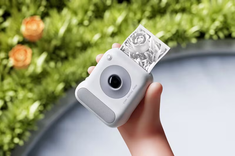
Image 1. Concept of the project Courtesy of TrendHunter
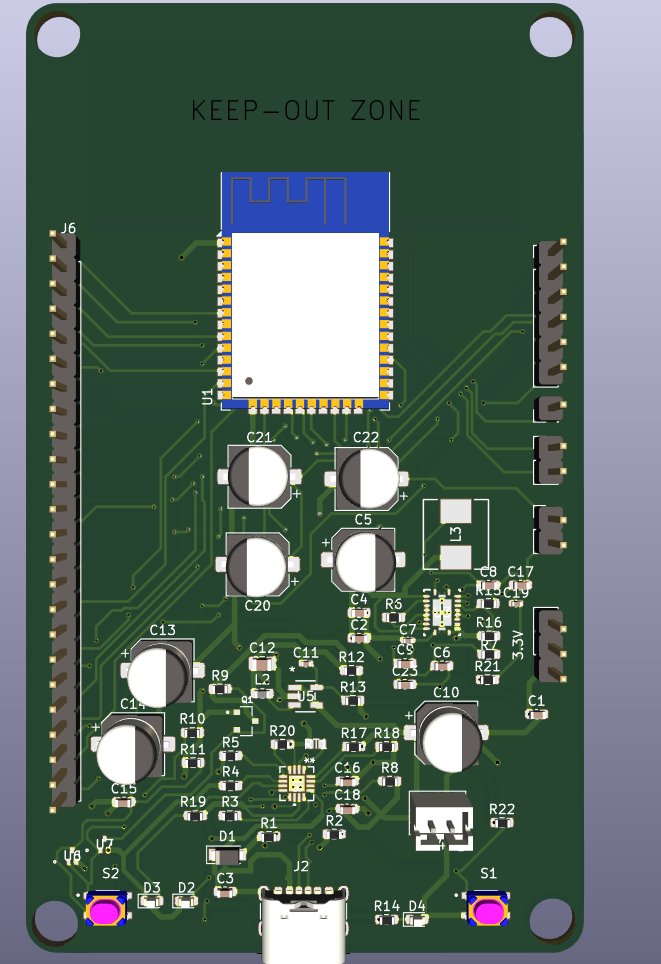 Image 2. Top view of PCB
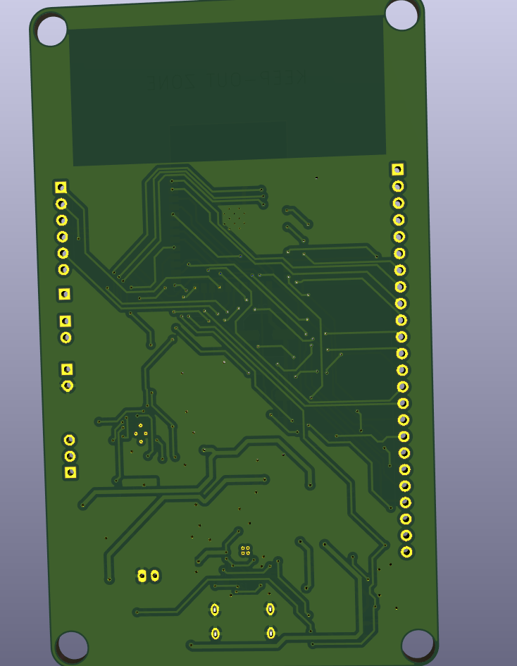 Image 3. Bottom view of PCB
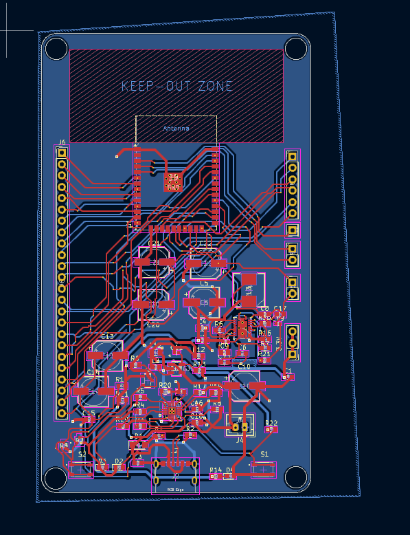 Image 4. PCB Layout & Connections
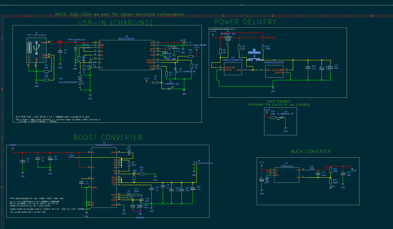 Image 5. Power Schematic of the PCB
P.S. The PCB was mainly used for creating a power management module just for this. The rest are pretty much built-in modules to buy.
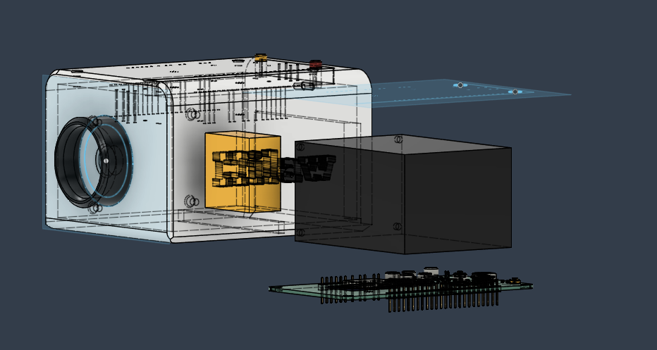 Image 6. Exploded View of the CAD
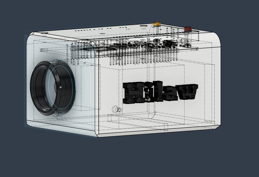 Image 7. Side View of the CAD
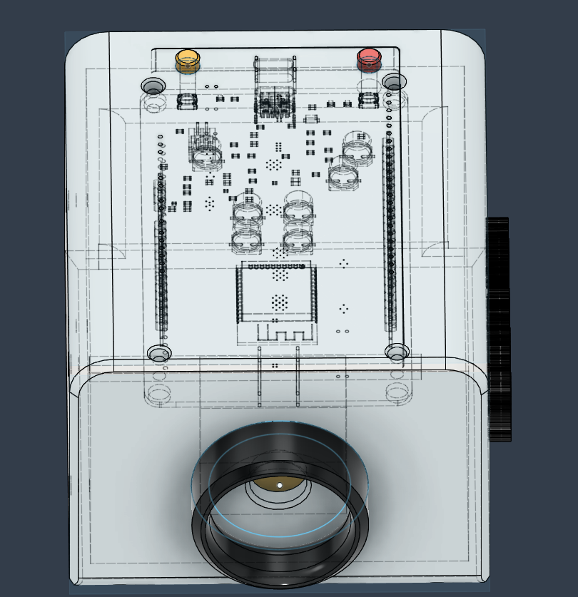 Image 8. Top view of the CAD
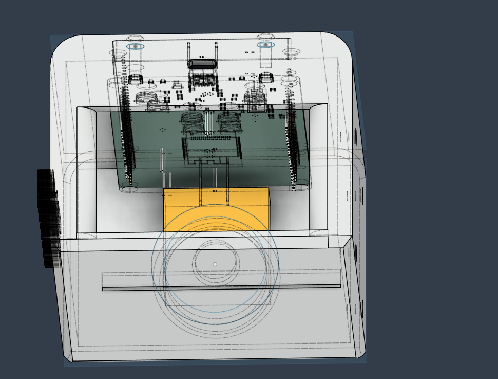 Image 9. Bottom View of the CAD
In terms of 3D Printing this project, I will print this in Resin since some of these are curved (also the lens cutout is circular). You may print this in Resin with the following parameters:
Layer height: 0.05mm
Orientation: 30-45 degrees
thats pretty much it
Have not yet started on the firmware. I am going to choose the Arduino IDE in order to program the ESP32-WROOM-32 since it is much more convenient for prototyping.
| Qty | Value | Footprint | References |
|---|---|---|---|
| 7 | 1µ | Capacitor_SMD:C_0603_1608Metric | C1, C2, C3, C4, C6, C8, C17 |
| 7 | 22µ | Capacitor_SMD:CP_Elec_6.3x5.4 | C5, C10, C13, C14, C20, C21, C22 |
| 5 | 10k | Resistor_SMD:R_0603_1608Metric | R4, R5, R18, R20, R22 |
| 4 | 1k | Resistor_SMD:R_0603_1608Metric | R3, R8, R17, R19 |
| 3 | 4.7μ | Capacitor_SMD:C_0603_1608Metric | C15, C16, C18 |
| 3 | XL-1608PGC-06 | LED_SMD:LED_0603_1608Metric | D2, D3, D4 |
| 2 | 0.1µ | Capacitor_SMD:C_0603_1608Metric | C9, C23 |
| 2 | 10K | Resistor_SMD:R_0603_1608Metric | R9, R10 |
| 2 | 56K | Resistor_SMD:R_0603_1608Metric | R1, R2 |
| 2 | Conn_01x02_Pin | Connector_PinHeader_2.54mm:PinHeader_1x02_P2.54mm_Vertical | J5, J9 |
| 2 | MMBT2222AM3T5G | MMBT2222AM3T5G:SOT-723_0P85X1P25_ONS-M | U6, U7 |
| 2 | SKRPABE010 | SW_SKRPABE010:SW_SKRPABE010 | S1, S2 |
| 1 | 100k | Resistor_SMD:R_0603_1608Metric | R14 |
| 1 | 10µ | Capacitor_SMD:C_0805_2012Metric | C12 |
| 1 | 2.2µ | FXL0630-2R2-M:IND_FXL0630_CMT | L3 |
| 1 | 2.2µ | Inductor_SMD:L_0603_1608Metric | L2 |
| 1 | 240k | Resistor_SMD:R_0603_1608Metric | R12 |
| 1 | 2N7002BK, 215 | 2N7002BK_215:TRANS_PMV130ENEAR | Q1 |
| 1 | 30k | Resistor_SMD:R_0603_1608Metric | R15 |
| 1 | 310k | Resistor_SMD:R_0603_1608Metric | R6 |
| 1 | 330K | Resistor_SMD:R_0603_1608Metric | R7 |
| 1 | 4.1p | Capacitor_SMD:C_0402_1005Metric | C11 |
| 1 | 47n | Capacitor_SMD:C_0402_1005Metric | C7 |
| 1 | 4k7 | Resistor_SMD:R_0603_1608Metric | R16 |
| 1 | 53.6k | Resistor_SMD:R_0603_1608Metric | R13 |
| 1 | 700K | Resistor_SMD:R_0603_1608Metric | R11 |
| 1 | 87p | Capacitor_SMD:C_0402_1005Metric | C19 |
| 1 | 910k | Resistor_SMD:R_0603_1608Metric | R21 |
| 1 | BQ24075RGTR | BQ24075RGTR:RGT16_1P7X1P7 | U8 |
| 1 | Conn_01x01_Pin | Connector_PinHeader_2.54mm:PinHeader_1x01_P2.54mm_Vertical | J10 |
| 1 | Conn_01x03_Pin | Connector_PinHeader_2.54mm:PinHeader_1x03_P2.54mm_Vertical | J7 |
| 1 | Conn_01x06_Pin | Connector_PinHeader_2.54mm:PinHeader_1x06_P2.54mm_Vertical | J8 |
| 1 | Conn_01x24_Pin | Connector_PinHeader_2.54mm:PinHeader_1x24_P2.54mm_Vertical | J6 |
| 1 | ESP32-WROOM-32 | RF_Module:ESP32-WROOM-32 | U1 |
| 1 | NCU18XH103F6SRB | NCU:TRES_NCU18XH103F6SRB_MUR | RT1 |
| 1 | PTVS17VS1UR,115 | Diode_SMD:Nexperia_CFP3_SOD-123W | D1 |
| 1 | RT8059GJ5 | RT8059GJ5:TSOT-23-5_RIT | U5 |
| 1 | TPS61088RHLR | TPS61088RHLR:RHL0020A | U3 |
| 1 | TYPE-C 6P LCH10.0 | Connector_USB:USB_C_Receptacle_GCT_USB4125-xx-x-0190_6P_TopMnt_Horizontal | J2 |
| 1 | USE-702528-500PCBJST | Connector_JST:JST_PH_B2B-PH-K_1x02_P2.00mm_Vertical | J4 |
Niqtan/Pagtingin-to-Highway
Version of Pagtingin Repo for Hack Club's Highway Program


motor-and-motion-control-lab/mmlab-12PhaseDrive-388Slave
PCB Electronics for Humanoid Robots and Bearingless Motor Systems

collins-emasi/KiCAD-PROJECTS-PCB
In this repository, I will be sharing some of the project I'm working on with KiCAD software.

plane-watch/hardware
Hardware-based ADS-B receiver and decoder for a HelloFPGA Smart ZYNQ SL board

aaronsilinskas/aura-prototype
A monorepo to prototype Aura Game Engine core features.

0BitsnBytes/McQueen
an overpowered rc car that poses a danger to my safety :)
It measures 60.5 × 103 mm and has 2 copper layers, 1.6 mm thick.
69 parts, built around the ESP32-WROOM-32, RT8059GJ5, TPS61088RHLR and MMBT2222AM3T5G-MS. The full list of its parts is on this page, with links to each part's symbol and footprint where PCBKit's library has them.
From the Niqtan/Hilaw repository on GitHub, at the commit this page was made from: the board is PCB/Polaroid_Cam.kicad_pcb and its schematic PCB/Polaroid_Cam.kicad_sch. PCBKit opens the board in the browser, with nothing to install.
Its repository publishes it under the MIT licence: you may reuse it on that licence's terms (keep the author's notice, and for a copyleft licence share your changes alike).