2 layers60 × 30 mm
Controller
google/mozc-devices
Circuit diagrams and firmware source code for Gboard DIY keyboards
11 parts3kApache-2.0
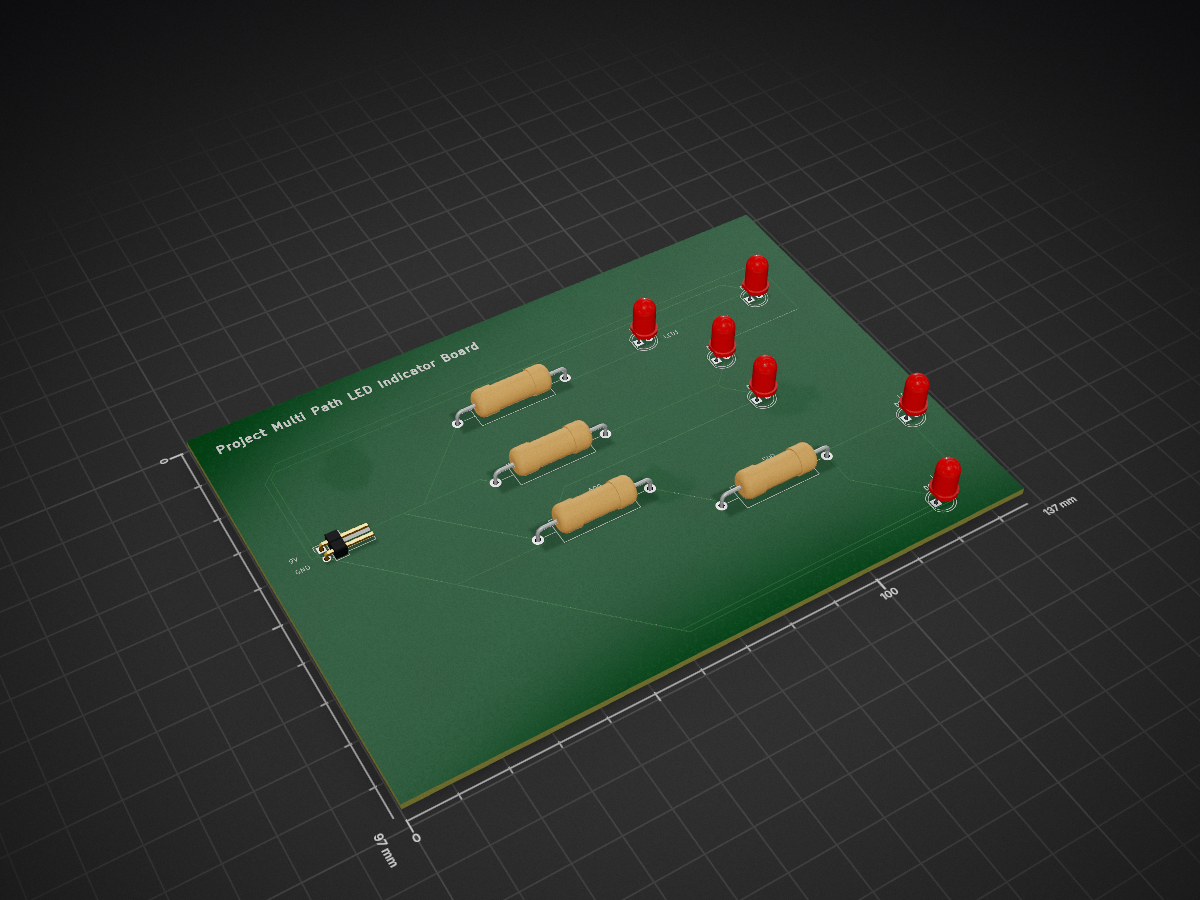
 Nikolov999/Project-Multi-Path-LED-Indicator-Board
A 9 V through-hole KiCad project created as a self-directed exercise in mixed series/parallel circuit analysis, resistor sizing, current splitting, PCB design, and design verification.
Project Multi Path LED Indicator Board is an open-source printed circuit board by Nikolov999, from the Nikolov999/Project-Multi-Path-LED-Indicator-Board repository on GitHub. It is a 2-layer board of 137 × 97 mm with 11 parts on 7 nets, routed with 51 tracks and 0 vias.
Its parts include 6 diodes, 4 resistors and 1 connector.
A 9 V through-hole KiCad project created as a self-directed exercise in mixed series/parallel circuit analysis, resistor sizing, current splitting, PCB design, and design verification.
The project deliberately combines different branch structures rather than repeating the same resistor-and-LED branch six times.
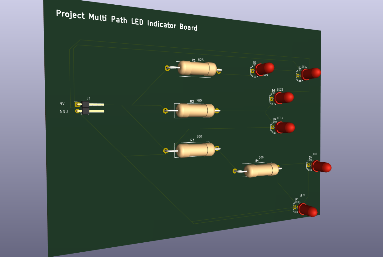
The exercise brief was generated by ChatGPT (OpenAI, GPT-5.6 Sol) at the my request as part of a hands-on electronics learning session.
I then independently selected the final topology, performed the branch calculations, created and corrected the schematic, assigned footprints, routed the PCB, added silkscreen, and completed the KiCad design workflow with review.
My polished user request is preserved in docs/user-request.md, and the revised six-LED exercise brief is preserved in docs/project-brief-chatgpt.md.
| Parameter | Value |
|---|---|
| Supply voltage | 9 V |
| Desired total current | ≈ 24 mA |
| Assumed LED forward voltage | ≈ 2 V |
| LEDs | 6 |
| Construction | Through-hole |
| PCB | 2-layer |
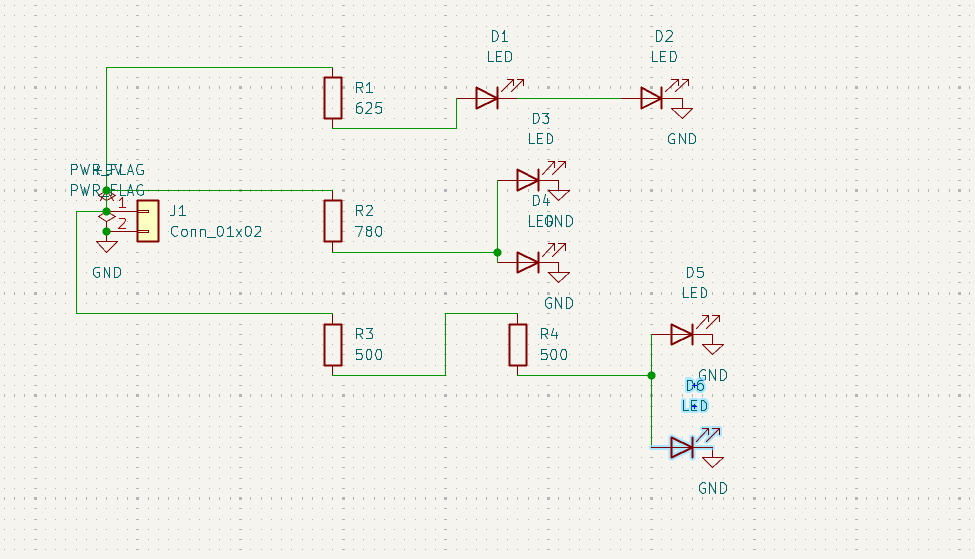
+9V -> R1 625Ω -> D1 -> D2 -> GNDD1 and D2 are in series, so their forward-voltage drops add.
                         +-> D3 -> GND
+9V -> R2 780Ω -> node
                         +-> D4 -> GND
The branch current reaches a junction and splits between D3 and D4.
                                      +-> D5 -> GND
+9V -> R3 500Ω -> R4 500Ω -> node
                                      +-> D6 -> GND
R3 and R4 are in series, giving a total resistance of 1000 Ω before the current splits between D5 and D6.
| Branch | Resistor arrangement | LED arrangement | Approx. branch current |
|---|---|---|---|
| 1 | R1 = 625 Ω | D1 + D2 series | 8.00 mA |
| 2 | R2 = 780 Ω | D3 / D4 parallel | 8.97 mA total |
| 3 | R3 + R4 = 1000 Ω | D5 / D6 parallel | 7.00 mA total |
Approximate total current:
It ≈ 8.00 + 8.97 + 7.00
It ≈ 23.97 mA
This closely matches the 24 mA design target.
Full derivations are in docs/calculations.md.
Branches 2 and 3 use parallel LEDs sharing upstream current-limiting resistance.
The calculations assume identical LEDs and equal current sharing. Real LEDs have forward-voltage tolerances, so current will not necessarily divide equally. One LED can conduct more current than the other.
For a robust real-world design, each parallel LED would normally use its own resistor or an appropriate constant-current circuit.
This topology is intentionally retained as a learning example because it demonstrates the difference between:
See docs/design-limitations.md.
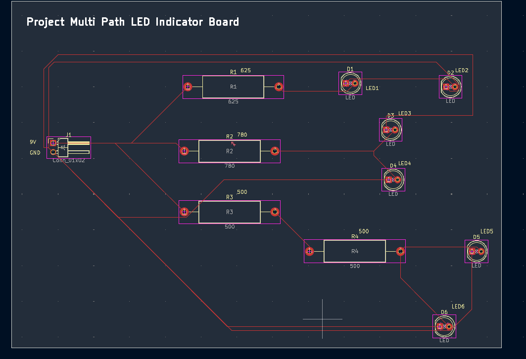
The current board is a through-hole design using a 1.6 mm, 2-layer PCB definition. The routed design contains no vias.
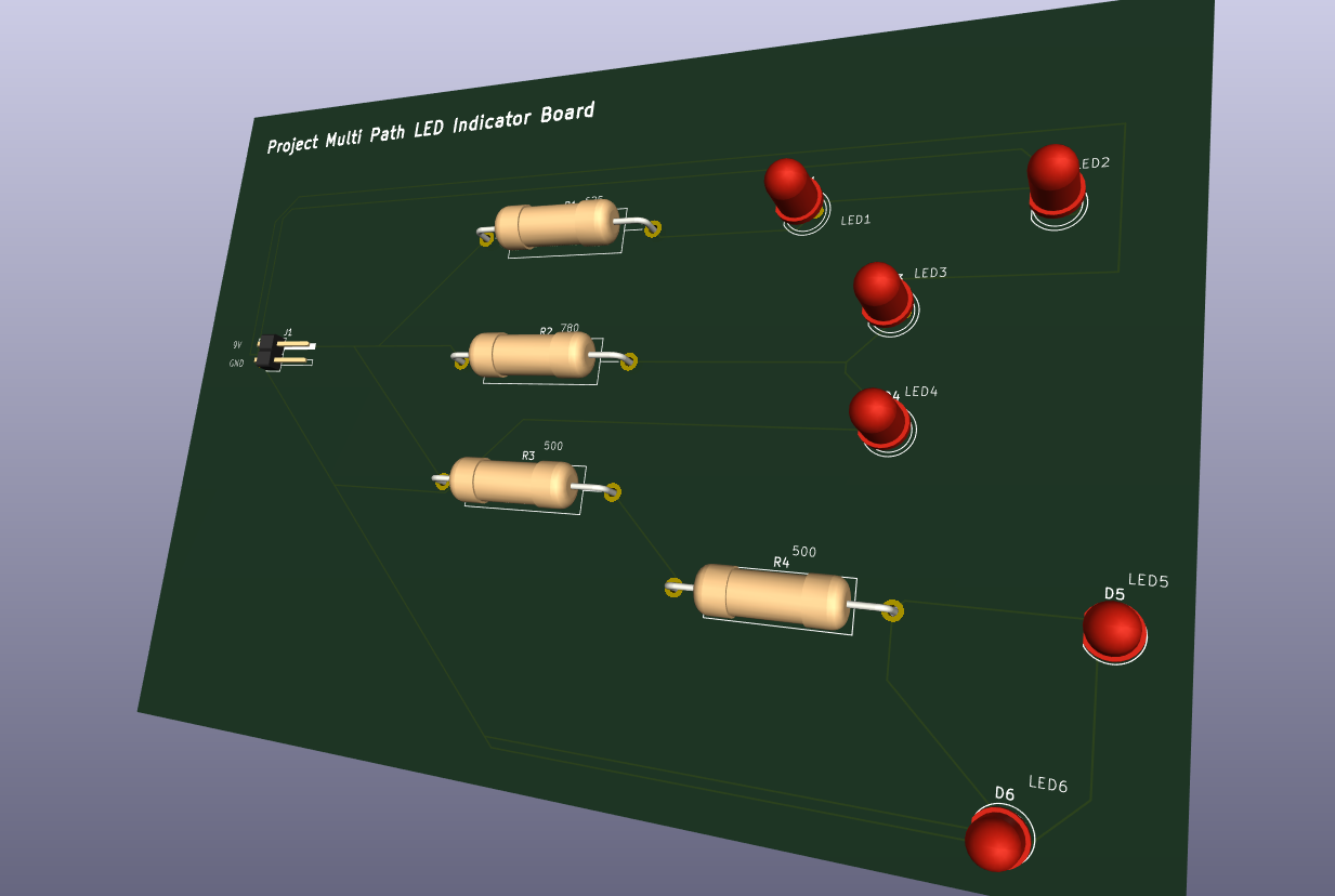
See BOM.csv.
Main components:
Source files are under kicad/:
Project-Multi-Path-LED-Indicator-Board.kicad_pro
Project-Multi-Path-LED-Indicator-Board.kicad_sch
Project-Multi-Path-LED-Indicator-Board.kicad_pcb
The local .kicad_prl preferences file is intentionally excluded from version control.
The design workflow includes:
Final Gerber and drill files are included under fabrication/.
A manufacturer-ready convenience package is also included:
fabrication/Project-Multi-Path-LED-Indicator-Board-Gerbers.zipThe export includes copper, solder-mask, silkscreen, paste, board-outline, Gerber-job, PTH drill, and NPTH drill files. Because this is a through-hole board, the paste layers are not required for normal manual assembly but are retained as part of the complete KiCad export.
.
├── README.md
├── BOM.csv
├── .gitignore
├── .gitattributes
├── kicad/
├── docs/
├── images/
└── fabrication/This project was built to strengthen:
| Qty | Value | Footprint | References |
|---|---|---|---|
| 6 | LED | LED_THT:LED_D5.0mm | D1, D2, D3, D4, D5, D6 |
| 2 | 500 | Resistor_THT:R_Axial_DIN0617_L17.0mm_D6.0mm_P25.40mm_Horizontal | R3, R4 |
| 1 | 625 | Resistor_THT:R_Axial_DIN0617_L17.0mm_D6.0mm_P25.40mm_Horizontal | R1 |
| 1 | 780 | Resistor_THT:R_Axial_DIN0617_L17.0mm_D6.0mm_P25.40mm_Horizontal | R2 |
| 1 | Conn_01x02 | Connector_PinHeader_2.54mm:PinHeader_1x02_P2.54mm_Horizontal | J1 |
google/mozc-devices
Circuit diagrams and firmware source code for Gboard DIY keyboards


FrameworkComputer/ExpansionCards
Reference designs and documentation to create Expansion Cards for the Framework Laptop

hoglet67/RGBtoHDMI
Bare-metal Raspberry Pi project that provides pixel-perfect sampling of Retro Computer RGB/YUV video and conversion to HDMI

hackclub/OnBoard
💡 Join 1,000 teenagers and make your first PCB with a $100 grant!


tardate/LittleArduinoProjects
a collection of "Little Electronic & Arduino Projects", most involving electronics or an Arduino in one way or another!

basilfx/TRADFRI-Hacking
Hacking IKEA TRÅDFRI products, such as light bulbs, window blinds and other accessories.
It measures 137 × 97 mm and has 2 copper layers, 1.6 mm thick.
11 parts. The full list of its parts is on this page, with links to each part's symbol and footprint where PCBKit's library has them.
From the Nikolov999/Project-Multi-Path-LED-Indicator-Board repository on GitHub, at the commit this page was made from: the board is kicad/Project-Multi-Path-LED-Indicator-Board.kicad_pcb and its schematic kicad/Project-Multi-Path-LED-Indicator-Board.kicad_sch. PCBKit opens the board in the browser, with nothing to install.
Its repository states no licence, so its author keeps all rights: ask Nikolov999 before reusing the design.