2 layers30 × 35 mm
 NandXor96/USBWLEDC40
USB WLED Controller
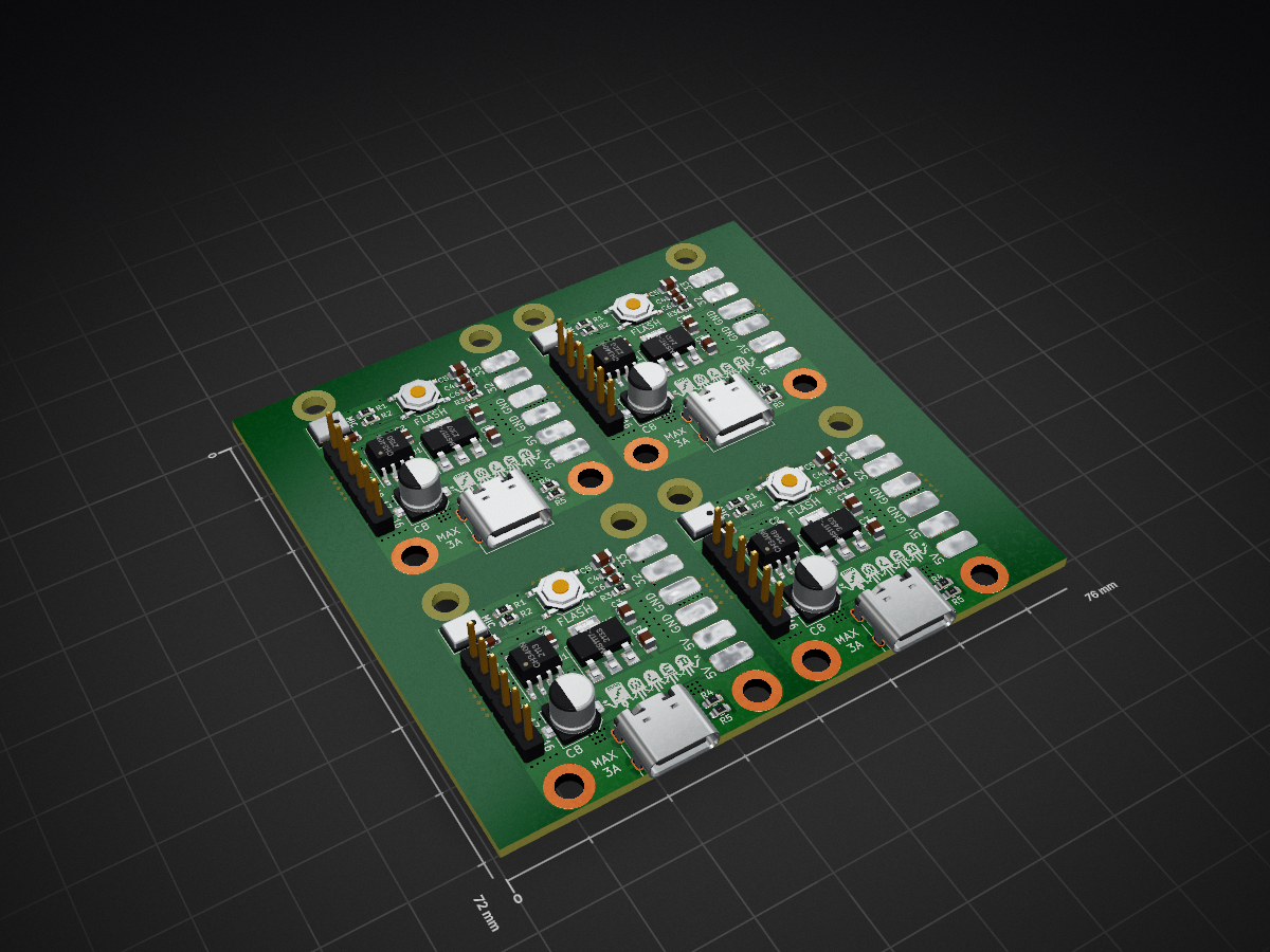
Panel is an open-source printed circuit board by NandXor96, from the NandXor96/USBWLEDC repository on GitHub. It is a 2-layer board of 76 × 72 mm with 184 parts on 180 nets, routed with 680 tracks and 400 vias.
It is built around the ESP32-WROOM-32E-N4, CH340N and AMS1117-3.3, with the CC0603KRX7R9BB104, CL21A106KAYNNNE and 0603WAF1002 among its other parts. Its parts include 32 capacitors, 32 connectors, 20 resistors, 12 ICs and 4 switches. It belongs with the ESP32 boards of this library.


USB Sound Reactive WLED Controller


To enter the Flash mode of the USBWLEDC, simply hold down the button as you connect the USB cable to a computer.
| Name | Value |
|---|---|
| LED Output 1: GPIO | 32 |
| LED Output 2: GPIO | 33 |
| Button 0: GPIO | 0 |
| Digitalmic: Type | Generic I2S PDM |
| Digitalmic: Pin I2S SD | GPIO 23 |
| Digitalmic: Pin I2S WS | GPIO 22 |
| Designators | Footprint | Quantity | Value | LCSC Part # |
|---|---|---|---|---|
| C1*, C2, C4 | Capacitor_SMD:C_0603_1608Metric | 3 | 100nF | C14663 |
| C3, C5, C7 | Capacitor_SMD:C_0805_2012Metric | 3 | 10uF | C15850 |
| C6 | Capacitor_SMD:C_0603_1608Metric | 1 | 1uF | C15849 |
| C8 | Capacitor_SMD:CP_Elec_5x5.4 | 1 | 100uF | C131115 |
| J10 | Connector_USB:USB_C_Receptacle_G-Switch_GT-USB-7010ASV | 1 | USB-C Receptacle | C2988369 |
| MK1* | Microphone:Microphone-6pin | 1 | GSA4737 MEMS Microphone | C5142171 |
| R1* | Resistor_SMD:R_0603_1608Metric | 1 | 100k | C25803 |
| R2, R3 | Resistor_SMD:R_0603_1608Metric | 2 | 10k | C25804 |
| R4, R5 | Resistor_SMD:R_0603_1608Metric | 2 | 5.1k | C23186 |
| SW1 | Button_Switch_SMD:SW_Push_1P1T_XKB_TS-1187A | 1 | Push Button Flash | C318884 |
| U1 | Package_SO:SOP-8_3.9x4.9mm_P1.27mm | 1 | CH340N | C2977777 |
| U2 | Package_TO_SOT_SMD:SOT-223-3_TabPin2 | 1 | AMS1117-3.3 | C6186 |
| U3** | RF_Module:ESP32-WROOM-32 | 1 | ESP32-WROOM-32 | C701341 |
* You can build it without the microphone. Then you don't need R1, C1 and MK1.
** The ESP32-WROOM Module can be purchased at a lower cost on AliExpress.
When ordering from JLCPCB, you have the option to get the front side of the board pre-populated - A service I strongly endorse. Subsequently, you'll only need to solder the ESP32-WROOM module onto the reverse side. With sufficient flux, this task can be accomplished with relative ease.
For those looking to populate the whole board, I suggest using a hot plate or a reflow oven for the front side.
Be careful to keep Isopropyl Alcohol away from the hole of the microphone when cleaning the board!The circuit board provided on this GitHub repository is offered "as is," without any warranties or guarantees of any kind. By accessing and utilizing this circuit board, you acknowledge and agree that you do so at your own risk.
The creator and contributor of this repository, shall not be held responsible or liable for any damages, losses, or injuries that may occur as a result of building and / or using this circuit board. This includes but is not limited to any direct, indirect, consequential, or incidental damages.
Electricity is dangerous. Only attempt this project if you know what you're doing.
| Qty | Value | Footprint | References |
|---|---|---|---|
| 60 | NPTH | NPTH | KiKit_MB_1_1, KiKit_MB_10_1, KiKit_MB_10_2, KiKit_MB_10_3, KiKit_MB_10_4, KiKit_MB_10_5, KiKit_MB_11_1, KiKit_MB_11_2, KiKit_MB_11_3, KiKit_MB_11_4, KiKit_MB_11_5, KiKit_MB_12_1, KiKit_MB_12_2, KiKit_MB_12_3, KiKit_MB_12_4, KiKit_MB_12_5 +44 |
| 16 | MountingHole | MountingHole:MountingHole_3.2mm_M3_DIN965_Pad | H1, H1, H1, H1, H2, H2, H2, H2, H3, H3, H3, H3, H4, H4, H4, H4 |
| 12 | 100nF | Capacitor_SMD:C_0603_1608Metric | C1, C1, C1, C1, C2, C2, C2, C2, C4, C4, C4, C4 |
| 12 | 10uF | Capacitor_SMD:C_0805_2012Metric | C3, C3, C3, C3, C5, C5, C5, C5, C7, C7, C7, C7 |
| 8 | 10k | Resistor_SMD:R_0603_1608Metric | R2, R2, R2, R2, R3, R3, R3, R3 |
| 8 | 5.1k | Resistor_SMD:R_0603_1608Metric | R4, R4, R4, R4, R5, R5, R5, R5 |
| 8 | 5V PAD | Library:SolderWirePad_1x01_SMD_3x6mm | J1, J1, J1, J1, J4, J4, J4, J4 |
| 8 | GND PAD | Library:SolderWirePad_1x01_SMD_3x6mm | J3, J3, J3, J3, J6, J6, J6, J6 |
| 4 | 100k | Resistor_SMD:R_0603_1608Metric | R1, R1, R1, R1 |
| 4 | 100uF | Capacitor_SMD:CP_Elec_5x5.4 | C8, C8, C8, C8 |
| 4 | 1uF | Capacitor_SMD:C_0603_1608Metric | C6, C6, C6, C6 |
| 4 | AMS1117-3.3 | Package_TO_SOT_SMD:SOT-223-3_TabPin2 | U2, U2, U2, U2 |
| 4 | Accessories | Connector_PinHeader_2.54mm:PinHeader_1x06_P2.54mm_Vertical | J7, J7, J7, J7 |
| 4 | CH340N | Package_SO:SOP-8_3.9x4.9mm_P1.27mm | U1, U1, U1, U1 |
| 4 | D1 PAD | Library:SolderWirePad_1x01_SMD_3x6mm | J2, J2, J2, J2 |
| 4 | D2 PAD | Library:SolderWirePad_1x01_SMD_3x6mm | J5, J5, J5, J5 |
| 4 | ESP32-WROOM-32 | RF_Module:ESP32-WROOM-32 | U3, U3, U3, U3 |
| 4 | FLASH_SW | Button_Switch_SMD:SW_Push_1P1T_XKB_TS-1187A | SW1, SW1, SW1, SW1 |
| 4 | GSA4737 | microphone:Microphone-6pin | MK1, MK1, MK1, MK1 |
| 4 | LOGO | LOGO | G***, G***, G***, G*** |
| 4 | USB_C_Receptacle_USB2.0 | Connector_USB:USB_C_Receptacle_G-Switch_GT-USB-7010ASV | J10, J10, J10, J10 |


matthiasnowak/jewelled
This is a panel meant for production of the Earrings, allowing for 2 Earrings per panel.


ossm-rs/ossm-rs-powerboard
Power management PCB for AIM family motors, designed to pair with the Industrial ESP32-S3-RS485-CAN control board by Waveshare and run with OSSM-RS software.
It measures 76 × 72 mm and has 2 copper layers, 1.57 mm thick.
184 parts, built around the ESP32-WROOM-32E-N4, CH340N, AMS1117-3.3 and CC0603KRX7R9BB104. The full list of its parts is on this page, with links to each part's symbol and footprint where PCBKit's library has them.
From the NandXor96/USBWLEDC repository on GitHub, at the commit this page was made from: the board is kicad/panel/panel.kicad_pcb and its schematic kicad/usbwledc.kicad_sch. PCBKit opens the board in the browser, with nothing to install.
Its repository states no licence, so its author keeps all rights: ask NandXor96 before reusing the design.