Skip to the content
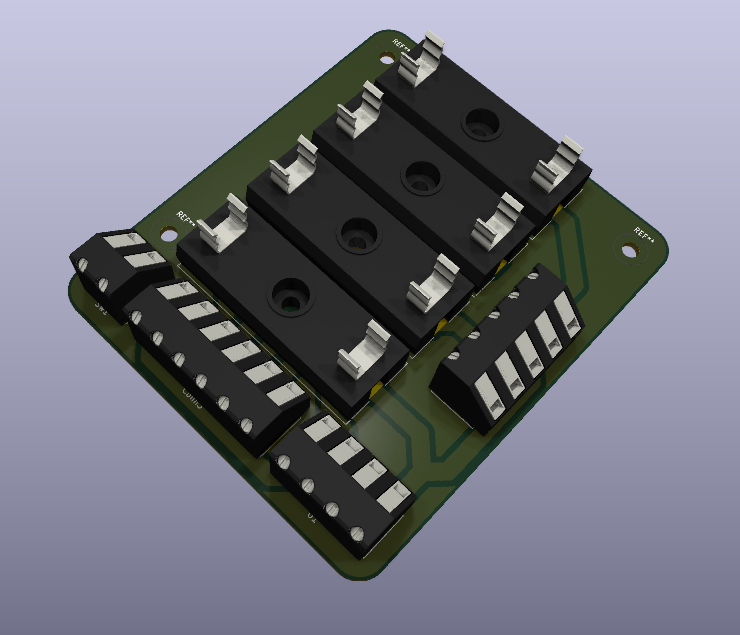
2 layers73 × 86 mmSnakeBench Schem, the printed circuit board in 3D

SnakeBench Schem

Nadoooor/SnakeBench

A snake-Styled Desktop Bench power supply

Size
73 × 86 mm
Copper layers
2
Thickness
1.6 mm
Parts
11
Nets
11
Pads
31
Tracks, vias
42, 0
Pours
1
Routed
Yes
KiCad
KiCad 10.0 (file 20260206)
Created
15 Jul 2026
Updated
18 Jul 2026

Overview

SnakeBench Schem is an open-source printed circuit board by Nadoooor, from the Nadoooor/SnakeBench repository on GitHub, published under the MIT licence. It is a 2-layer board of 73 × 86 mm with 11 parts on 11 nets, routed with 42 tracks and 0 vias.

Its parts include 4 fuses, 1 IC, 1 connector and 1 switch. It belongs with the power boards of this library.

README

README.md

SnakeBench


Centered Image


Description:

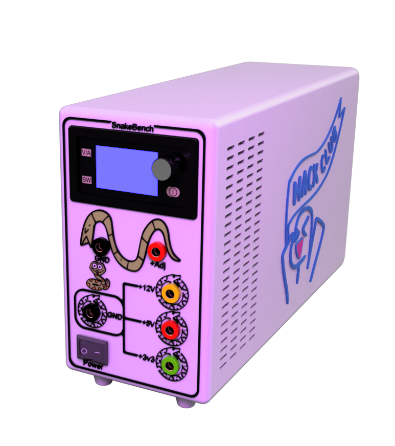
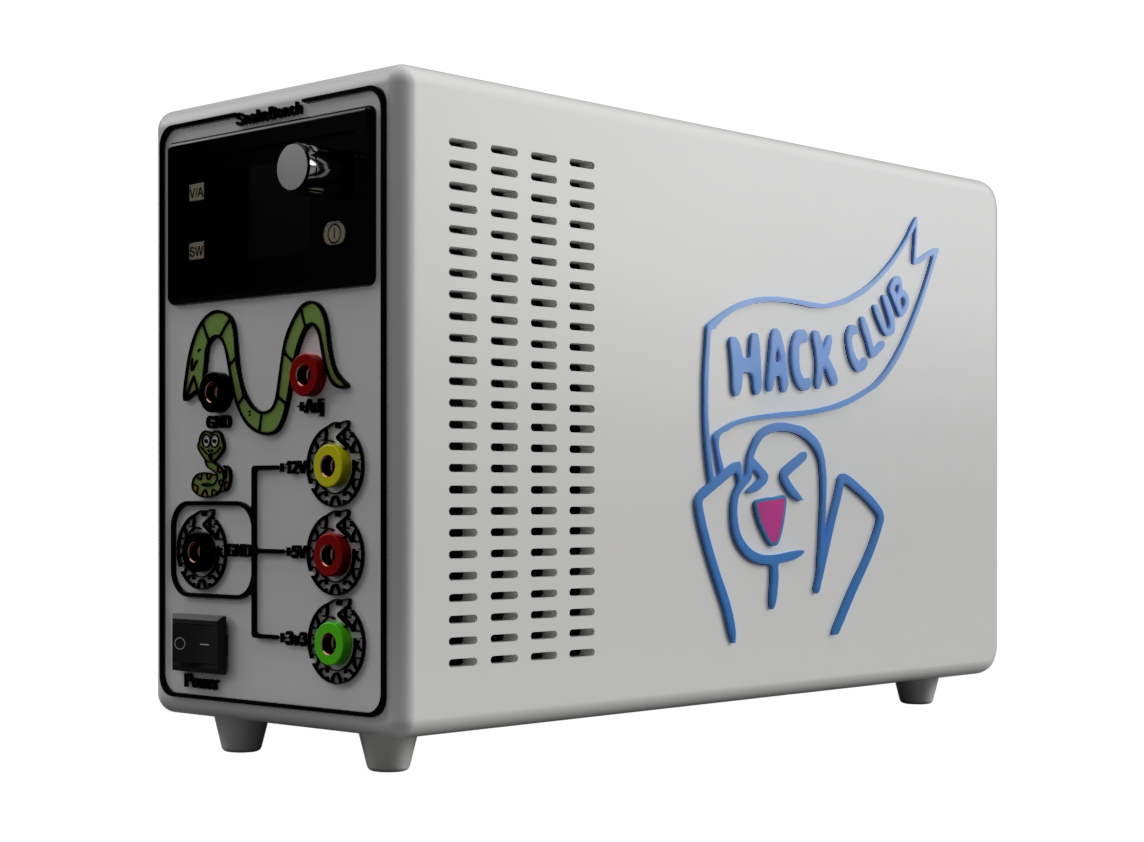
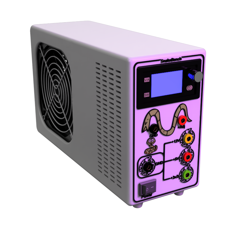
A snake-Styled Desktop Bench power supply, With adjustable Voltage, and fixed outputs, The project is Polished while working on the Panal Banana plugs places and shape. So every Snake, has its indication.

Why Iam Making this?

I have an old PC, and iam not using it anymore since i have another one. So, I decided to take components from it and convert them into Cool project.

So, Iam starting with this one, Converting a PSU into a Cool Bench Power Supply that will help me with my Hardware Projects, and of course making it in a Snake-Style.

Features:

  • Banana Plugs for easy connect.

  • Fixed Voltages came directly from the PSU.

    • +12V
    • +5V
    • 3v3
  • Adjustable voltage plug with a digital screen to show the readings.

  • Current limiting function.

  • Fuse Box limiting the current to 10A.

Photos:

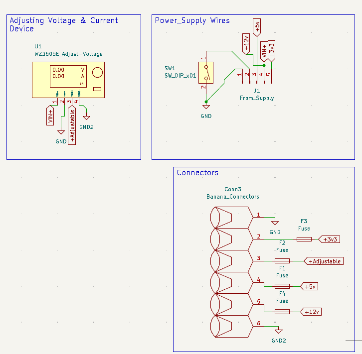
Schematic:

alt text

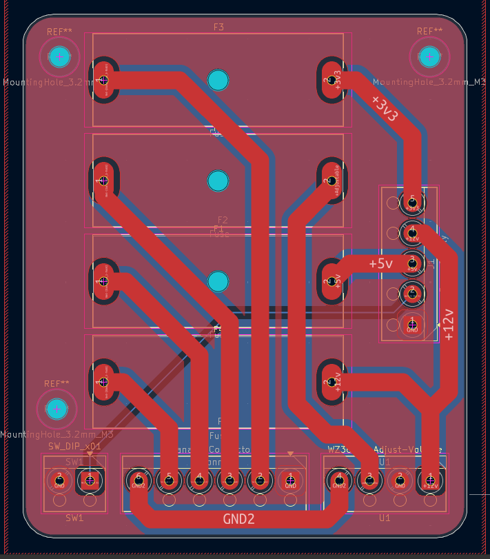
PCB:

alt text

3D PCB:

alt text

3D Assembly:

alt text

alt text

alt text

[!NOTE] Here You Go the Fusion Assembly Link

How To Build:

  1. Print all your parts.
  2. Solder the Fuse Holders and the terminals to the PCB.
  3. Add the Fuses to the Holders.
  4. Get your PSU and install it inside the Case.
  5. Rainforce it using the Screws from the back.
  6. Add your PCB on its place in the Case.
  7. Rainforce it using the Screws.
  8. get 4 or 5 of each fixed voltage wires and connect them inside each terminal_Block. (For each Voltage Bus)
  9. Take 3 or 4 wires of the Yellow wires (The 12V) and connect them to the input of the Voltage adjuster.
  10. Connect the GND to the adjuster and to one Black Banana Plug to use it as the GND of the fixed voltage buses.
  11. Connect the GND comming from the Adjuster to the one another Banana Plug to use it as the -Adj.
  12. Connect also the +Out of the adjuster to one Red Banana Plug to use it as the +Adj.
  13. Connect each Fixed Voltage bus to its banana Plug.
    • Yellow --> +12V
    • Red --> +5V
    • Green --> 3v3
  14. Rainforce all the Banana Plugs to the Front Panal.
  15. Rainforce the Adjuster to its place on top with its clips.
  16. Take the other Color printed Front Panal Drawings, and rainforce them with super glue each on its place.
  17. Do the same to Orphues on the right of the Back case.
  18. Take the button, and connect one terminal of it to 1 GND wire from the PSU, and the other terminal connect to the Green wire coming from the PSU (PS-ON).
  19. Rainforce it into the Panal using its clips.
  20. Review all the connections and make sure nothing shorted.
  21. Close the front panal with M2 Screws with the back case.
  22. Becareful and plug it for first time and try it.
  23. ENJOYYYY ;)

Made with ❤️, By @Nadoooor

Parts

11
QtyValueFootprintReferences
4FuseFuse:Fuseholder_Cylinder-6.3x32mm_Schurter_0031-8002_Horizontal_OpenF1, F2, F3, F4
1Banana_ConnectorsTerminalBlock_Altech:Altech_AK100_1x06_P5.00mmConn3
1From_SupplyTerminalBlock_Altech:Altech_AK100_1x05_P5.00mmJ1
1SW_DIP_x01TerminalBlock_Altech:Altech_AK100_1x02_P5.00mmSW1
1WZ3605E_Adjust-VoltageTerminalBlock_Altech:Altech_AK100_1x04_P5.00mmU1

The 8 most common of 11 parts.

Similar boards

  • 2 layers60 × 30 mmController, the printed circuit board in 3D

    Controller

    google/mozc-devices

    Circuit diagrams and firmware source code for Gboard DIY keyboards

    11 parts3kApache-2.0
  • 2 layers103 × 30.5 mmTS Front Endcap, the printed circuit board in 3D

    TS Front Endcap

    EEVengers/ThunderScope

    ThunderScope GitHub Repo

    11 parts1.3kMIT
  • 2 layers26 × 30 mmExpansion Card, the printed circuit board in 3D

    Expansion Card

    FrameworkComputer/ExpansionCards

    Reference designs and documentation to create Expansion Cards for the Framework Laptop

    11 parts1.1kCC-BY-4.0
  • 2 layers53.9 × 23.2 mmBuffer, the printed circuit board in 3D

    Buffer

    hoglet67/RGBtoHDMI

    Bare-metal Raspberry Pi project that provides pixel-perfect sampling of Retro Computer RGB/YUV video and conversion to HDMI

    11 parts1kGPL-3.0
  • 2 layers10 × 20 mm2 connector Sensor Board, the printed circuit board in 3D

    2 connector Sensor Board

    hackclub/OnBoard

    💡 Join 1,000 teenagers and make your first PCB with a $100 grant!

    11 parts915
  • 2 layersFet module, the printed circuit board in 3D

    Fet module

    ByteWelder/Decktility

    A handheld PC

    11 parts855CC-BY-SA-4.0
  • 2 layers47 × 33 mmSevensegment led display module, the printed circuit board in 3D

    Sevensegment led display module

    tardate/LittleArduinoProjects

    a collection of "Little Electronic & Arduino Projects", most involving electronics or an Arduino in one way or another!

    11 parts803MIT
  • 2 layers42.5 × 36.8 mmDevboard, the printed circuit board in 3D

    Devboard

    basilfx/TRADFRI-Hacking

    Hacking IKEA TRÅDFRI products, such as light bulbs, window blinds and other accessories.

    11 parts743CC-BY-4.0

Questions

How big is the SnakeBench Schem PCB?

It measures 73 × 86 mm and has 2 copper layers, 1.6 mm thick.

What parts does the SnakeBench Schem use?

11 parts. The full list of its parts is on this page, with links to each part's symbol and footprint where PCBKit's library has them.

Where can I download the SnakeBench Schem KiCad files?

From the Nadoooor/SnakeBench repository on GitHub, at the commit this page was made from: the board is PCB/SnakeBench_Schem.kicad_pcb and its schematic PCB/SnakeBench_Schem.kicad_sch. PCBKit opens the board in the browser, with nothing to install.

Can I use the SnakeBench Schem design in my own project?

Its repository publishes it under the MIT licence: you may reuse it on that licence's terms (keep the author's notice, and for a copyleft licence share your changes alike).