4 layers56.4 × 77.8 mm
 MorrisYLin/ASIC_II_PCB
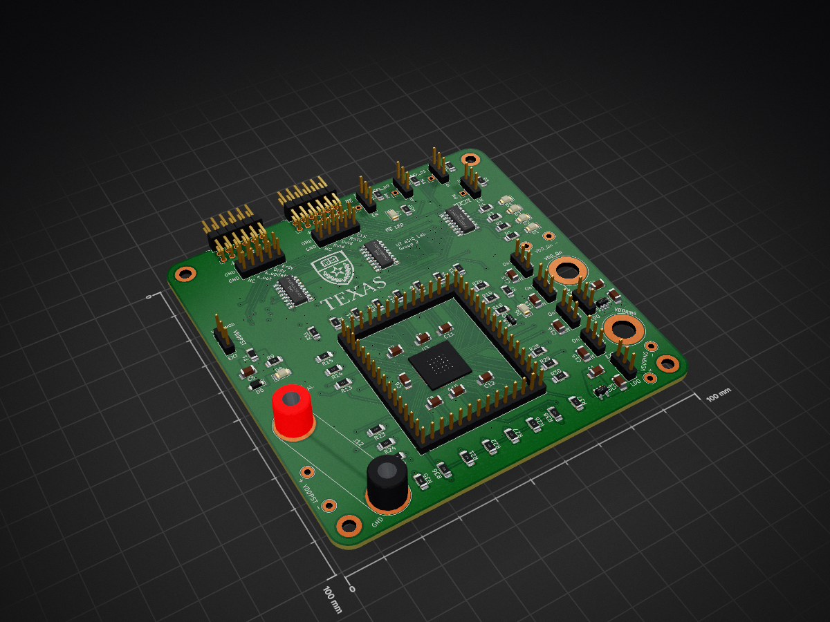
Lab 1 Morris Lin ASIC II is an open-source printed circuit board by MorrisYLin, from the MorrisYLin/ASIC_II_PCB repository on GitHub. It is a 4-layer board of 100 × 100 mm with 108 parts on 106 nets, routed with 1,381 tracks and 242 vias.
It is built around the TLV75710PDBV, BSS138 and PTVS3V3S1UR,115-JSM. Its parts include 39 resistors, 16 capacitors, 11 connectors, 9 ICs and 8 diodes.


| Qty | Value | Footprint | References |
|---|---|---|---|
| 32 | 10k | Resistor_SMD:R_1206_3216Metric_Pad1.30x1.75mm_HandSolder | R10, R11, R12, R13, R14, R15, R16, R17, R18, R19, R20, R21, R22, R23, R24, R25 +16 |
| 7 | 0.1u | Capacitor_SMD:C_1206_3216Metric_Pad1.33x1.80mm_HandSolder | C6, C7, C8, C9, C10, C11, C12 |
| 7 | 470 | Resistor_SMD:R_1206_3216Metric_Pad1.30x1.75mm_HandSolder | R1, R2, R3, R4, R7, R9, R39 |
| 7 | Jumper_3_Open | Connector_PinHeader_2.54mm:PinHeader_1x03_P2.54mm_Vertical | JP1, JP2, JP3, JP4, JP7, JP8, JP10 |
| 6 | 74CBTLV3253D,118 | ASIC_II:SOIC127P600X175-16N | IC1, IC2, IC3, IC4, IC5, IC6 |
| 6 | TestPoint | TestPoint:TestPoint_Loop_D2.54mm_Drill1.5mm_Beaded | TP1, TP2, TP3, TP4, TP5, TP6 |
| 5 | 10u | Capacitor_SMD:C_1206_3216Metric_Pad1.33x1.80mm_HandSolder | C5, C13, C14, C15, C16 |
| 4 | 1u | Capacitor_SMD:C_1206_3216Metric_Pad1.33x1.80mm_HandSolder | C1, C2, C3, C4 |
| 4 | Conn_01x14 | Connector_PinHeader_2.54mm:PinHeader_1x14_P2.54mm_Vertical | J8, J9, J10, J11 |
| 4 | Jumper_3_Open | ASIC_II:PinHeader_SP3T_P2.54mm_Vertical | JP5, JP6, JP9, JP11 |
| 4 | MountingHole | MountingHole:MountingHole_3.2mm_M3_DIN965_Pad_TopBottom | H1, H2, H3, H4 |
| 2 | LOGO | LOGO | G***, G*** |
| 2 | TLV75710PDBV | Package_TO_SOT_SMD:SOT-23-5 | U1, U2 |
| 1 | BSS138 | Package_TO_SOT_SMD:SOT-23 | Q1 |
| 1 | Logic_Analyzer_PMOD_A | ASIC_II:PinHeader_VertNum_2x05_P2.54mm_Vertical | J6 |
| 1 | Logic_Analyzer_PMOD_B | ASIC_II:PinHeader_VertNum_2x05_P2.54mm_Vertical | J7 |
| 1 | PMOD_A | ASIC_II:PinHeader_2x06_P2.54mm_Horizontal | J2 |
| 1 | PMOD_B | ASIC_II:PinHeader_2x06_P2.54mm_Horizontal | J3 |
| 1 | PTVS3V3S1UR,115 | Diode_SMD:Nexperia_CFP3_SOD-123W | D5 |
| 1 | Q1 | LED_SMD:LED_1206_3216Metric_Pad1.42x1.75mm_HandSolder | D1 |
| 1 | Q2 | LED_SMD:LED_1206_3216Metric_Pad1.42x1.75mm_HandSolder | D2 |
| 1 | Q3 | LED_SMD:LED_1206_3216Metric_Pad1.42x1.75mm_HandSolder | D3 |
| 1 | Q4 | LED_SMD:LED_1206_3216Metric_Pad1.42x1.75mm_HandSolder | D4 |
| 1 | SMDH1206B025TF | Fuse:Fuse_1206_3216Metric_Pad1.42x1.75mm_HandSolder | F1 |
| 1 | VDDPOC | LED_SMD:LED_1206_3216Metric_Pad1.42x1.75mm_HandSolder | D6 |
| 1 | VDDPST | LED_SMD:LED_1206_3216Metric_Pad1.42x1.75mm_HandSolder | D8 |
| 1 | VDDPST External | Connector:Banana_Jack_2Pin | J12 |
| 1 | VDDRING External | Connector:Banana_Jack_1Pin | J5 |
| 1 | VDD_Qn External | Connector:Banana_Jack_1Pin | J4 |
| 1 | ~ | ASIC_II:QFN56ASIC | U3 |
| 1 | ~{OE} | LED_SMD:LED_1206_3216Metric_Pad1.42x1.75mm_HandSolder | D9 |


Phunkafizer/RFM-gateway
Hard- and software for the RFM-gateway, a universal platform for integrating sub-GHz radio into your WiFi network


StuckAtPrototype/Racer
These are structured into their own files. I could have used submodules, but decided against it.

willem-pennings/balancing-cube
A cube that balances itself in a corner or edge using reaction wheels

abhishek-kakkar/BeagleLogic
A Software Suite that implements a logic analyzer with the PRU on the BeagleBone / BeagleBone Black.
It measures 100 × 100 mm and has 4 copper layers, 1.61 mm thick.
108 parts, built around the TLV75710PDBV, BSS138 and PTVS3V3S1UR,115-JSM. The full list of its parts is on this page, with links to each part's symbol and footprint where PCBKit's library has them.
From the MorrisYLin/ASIC_II_PCB repository on GitHub, at the commit this page was made from: the board is Lab_1_Morris_Lin_ASIC_II.kicad_pcb and its schematic Lab_1_Morris_Lin_ASIC_II.kicad_sch. PCBKit opens the board in the browser, with nothing to install.
Its repository states no licence, so its author keeps all rights: ask MorrisYLin before reusing the design.