2 layers57 × 55.2 mm
LogicAnalyzer
gusmanb/logicanalyzer
24 channel, 100Msps logic analyzer hardware and software
10 parts5.1kGPL-3.0

 MohnessWaizy/AutonomROS5
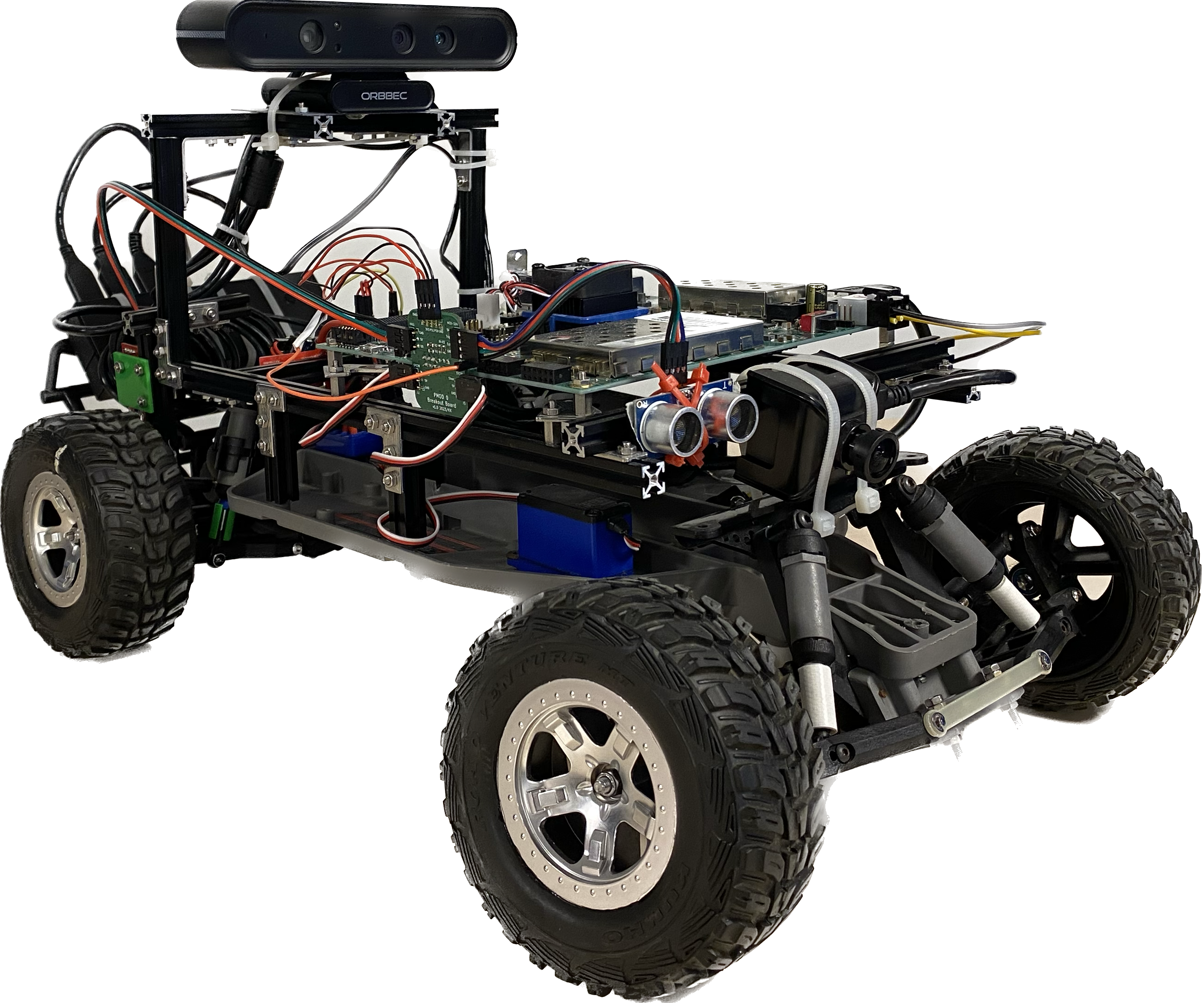
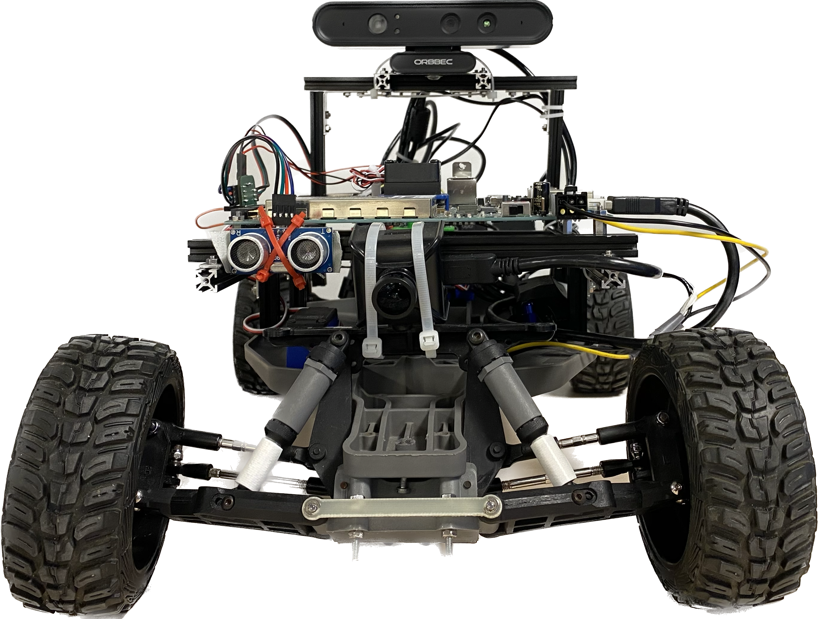
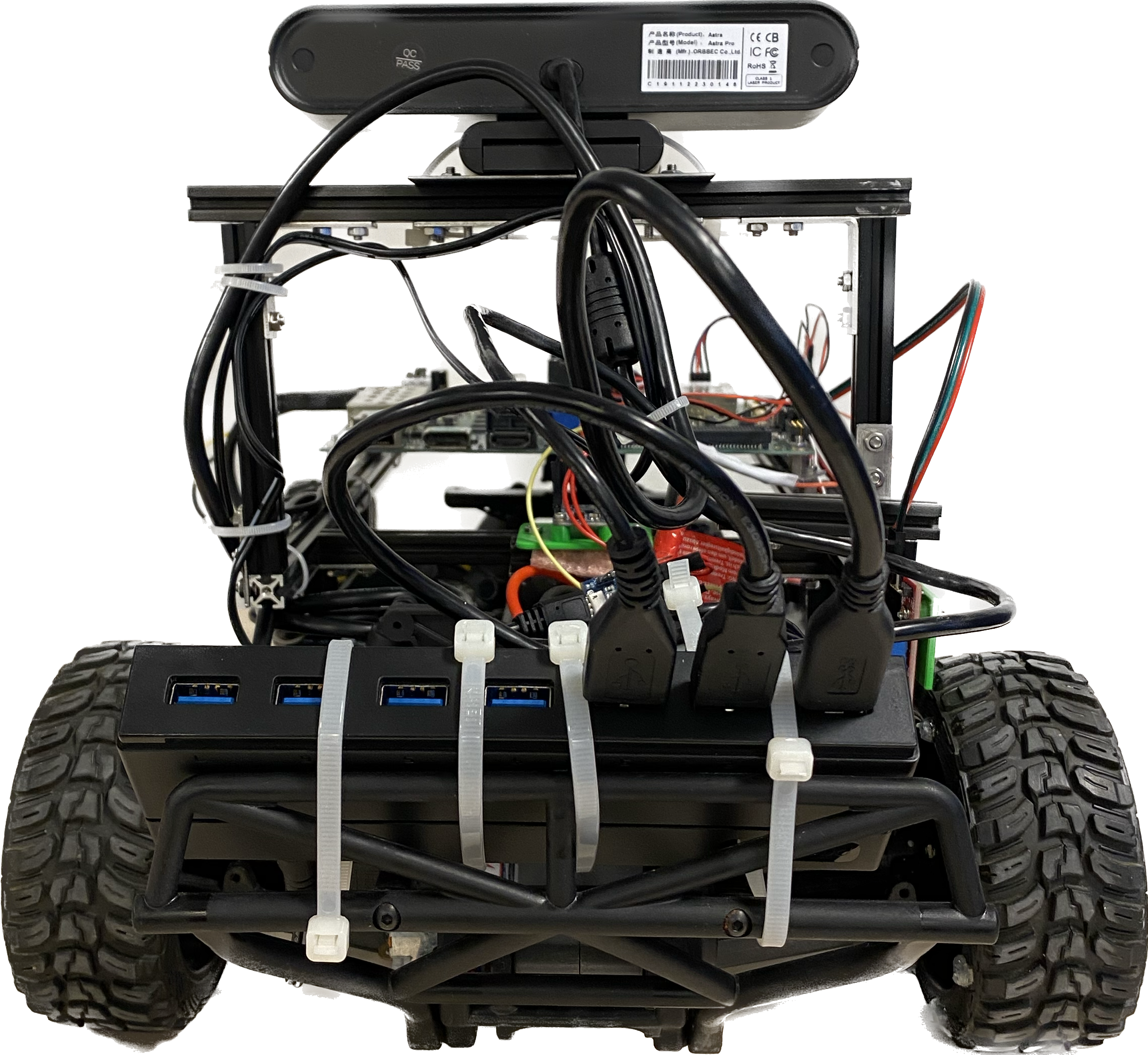
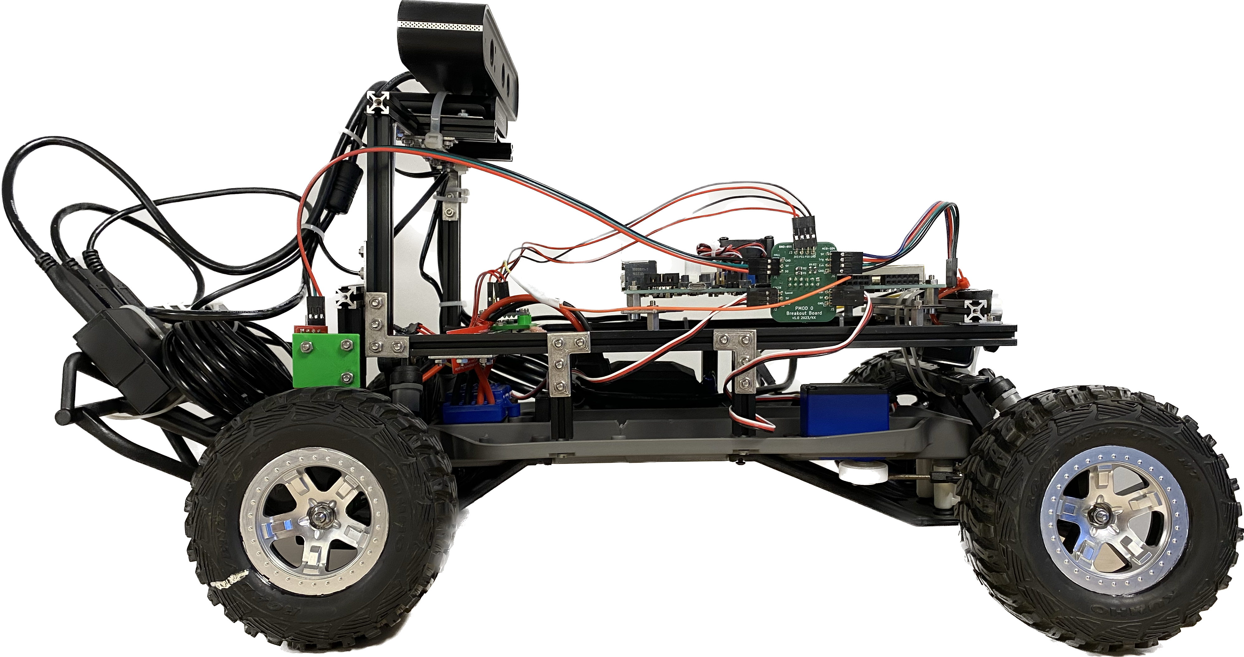
AutonomROS: Autonomous Car Swarm with Hardware-accelerated ROS Programming
ZCU104 Breakout is an open-source printed circuit board by MohnessWaizy, from the MohnessWaizy/AutonomROS repository on GitHub. It is a 2-layer board of 30 × 36.8 mm with 10 parts on 13 nets, routed with 35 tracks and 15 vias.
Its parts include 6 connectors and 4 resistors. It belongs with the interfaces and adapters boards of this library.
Paper: AutonomROS: A ReconROS-based Autonomonous Driving Unit
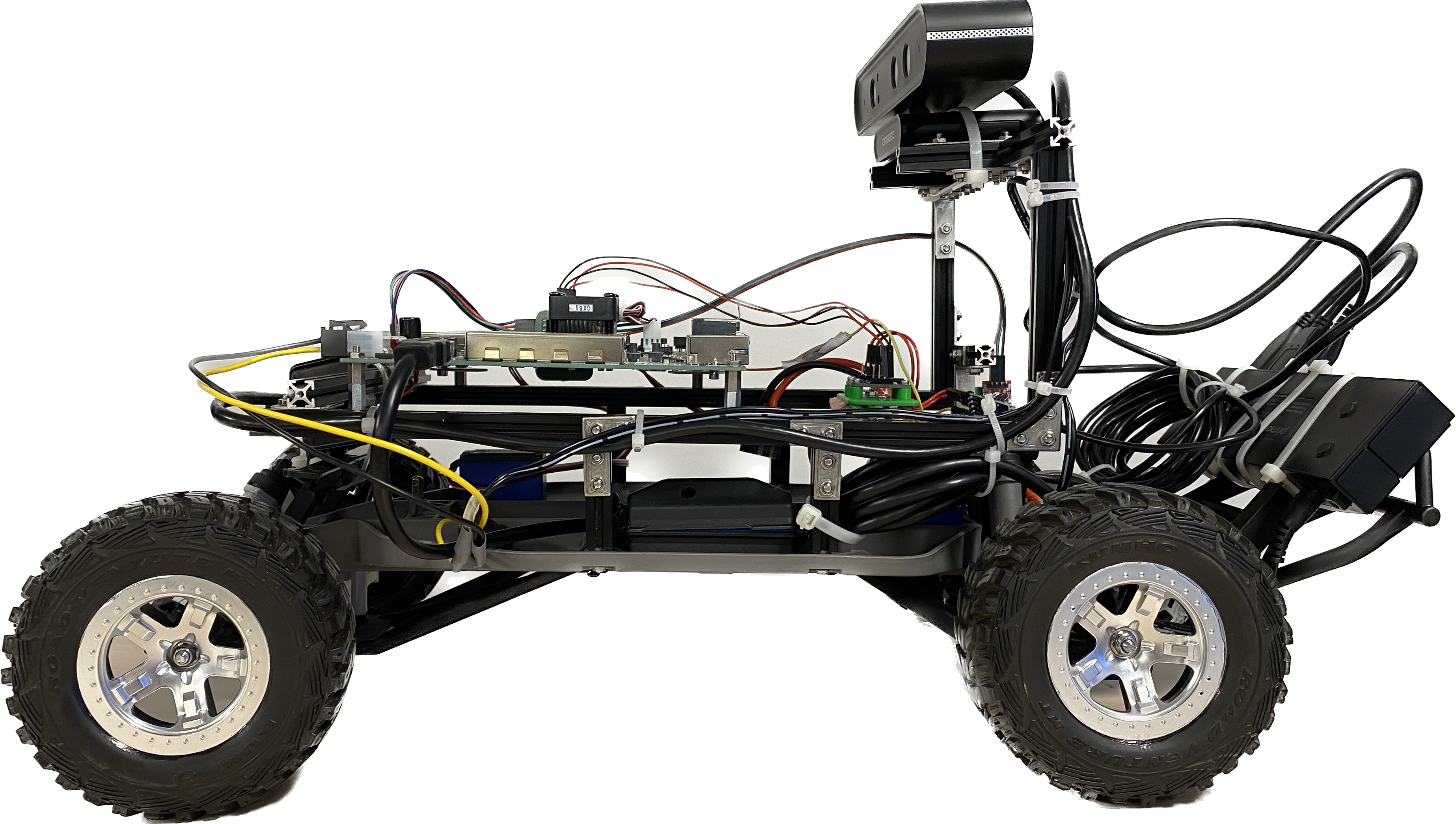
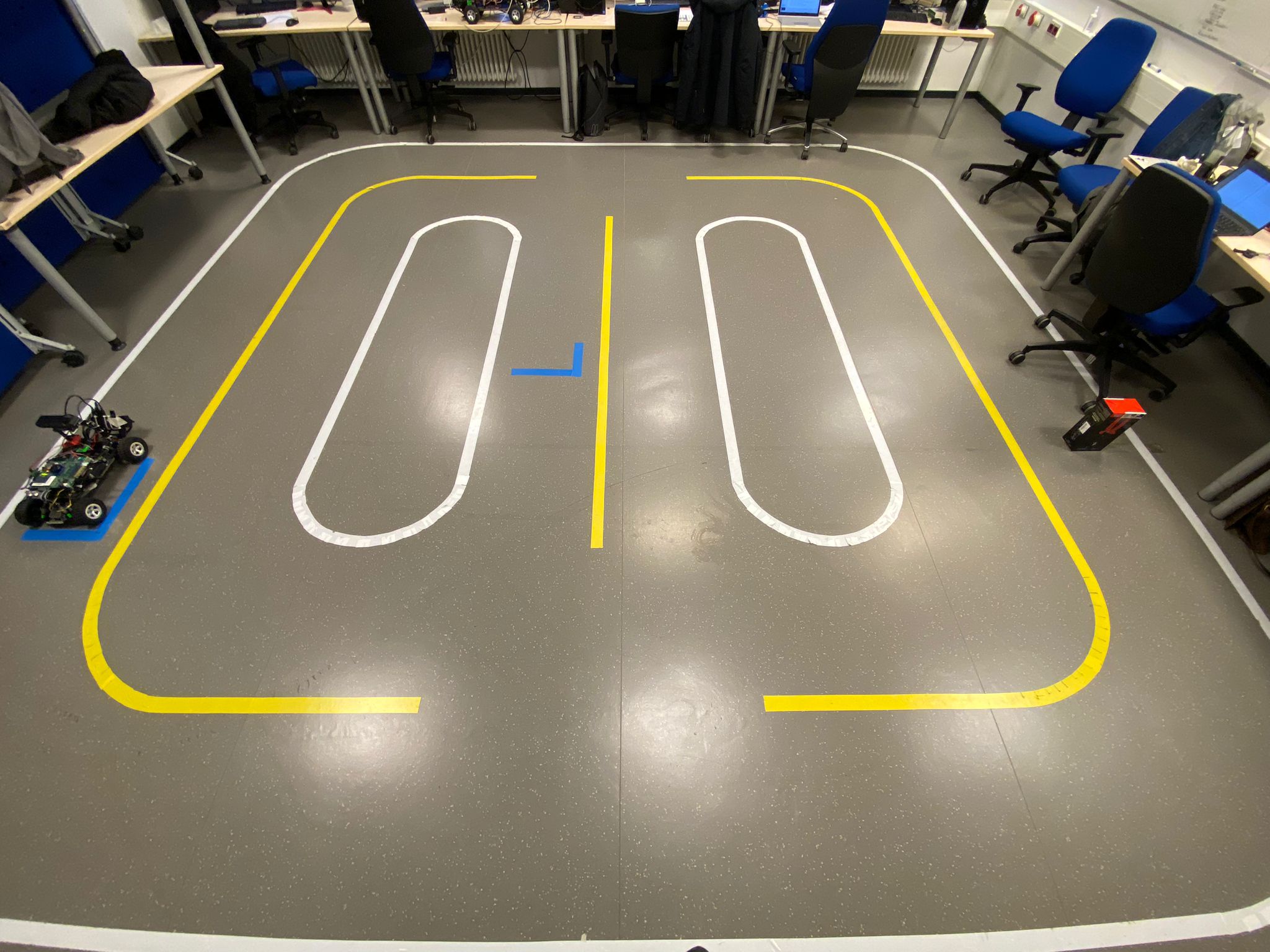
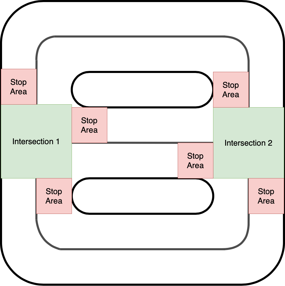
We present an Ackermann-based autonomous driving robot car based on an ROS 2 architecture alongside accelerated computationally intensive components using hardware acceleration through ReconROS on an Zynq UltraScale+ MPSoC ZCU104 FPGA board. First, our robot car can drive in a lane at a predefined speed. Second, it can detect obstacles and avoid collisions by stopping. Third, our car prevents intersection collisions with other vehicles by communicating via Wifi to a virtual traffic light offering smooth intersection coordination. Finally, since our developed architecture builds upon Navigation 2 (Nav2), a commonly used ROS 2 framework, we provide smooth integration and extendability. Furthermore, we accelerated three computationally intensive architecture components, lane detection, point cloud calculation, and obstacle detection, to save CPU time. In addition, we discovered that leveraging shared memory through Iceoryx as the ROS 2 middleware further reduced CPU time. Hence, we extended ReconROS’s capabilities by making it compatible with Iceoryx.
For more detailed information regarding dependencies consider the ansible folder
If git is not already installed on your computer, install it with:
sudo apt install gitgit clone git@git.uni-paderborn.de:clienen/autonomros.gitChange into the root of the repository and run the following command:
git submodule update --initWe provide a recommended way to install all requirements using Ansible, which might cause changes on your system. Otherwise look into the ansible playbooks and follow the steps manually.
You can either run our script first_install.sh or look into the documentation of Ansible.
!We do not provide any warranty for potential damages!
ansible/scripts/first_install.shsource ~/venvs/ansible/bin/activate
cd ansible/
ansible-playbook -i hosts.yml lab.yml -K --extra-vars "main_user_name=YOUR_USERNAME"Exchange YOUR_USERNAME with your local username. It is required that you have root access via sudo. The BECOME password is your password. You may get an error for the reconros : Build docker image step. If this is the case, restart your computer and run the ansible playbook again.
Go to Xilinx website and download Xilinx Unified Installer 2021.2: Linux Self Extracting Web Installer. Move the file into ~/ansible-files/. Then run the following commands:
cd ~/ansible-files/
chmod u+x ./Xilinx_Unified_2021.2_1021_0703_Lin64.bin
./Xilinx_Unified_2021.2_1021_0703_Lin64.bin -- -b AuthTokenGen
Here, you will be asked for your Xilinx Account Credentials. Next, you need to accept the Xilinx EULA and 3rd Party EULA. The following command accepts the EULAs, downloads, and installs Vivado (this may take some hours):
~/ansible-files/Xilinx_Unified_2021.2_1021_0703_Lin64.bin -- -b Install -c ~/ansible-files/install_config.txt -a XilinxEULA,3rdPartyEULATo install the Mosquitto broker and the Mosquitto command line tools, run:
sudo apt-get install mosquitto mosquitto-clients -yThe Mosquitto broker starts automatically after installing.
Run the following line to start the Mosquitto broker on each system start:
sudo systemctl enable mosquittoYou need to allow anonymous acces by editing /etc/mosquitto/mosquitto.conf and adding:
allow_anonymous trueBe aware of the security implications!
The mosquitto server must be accessible by the board. You can listen on all interfaces by adding the following to the configuration.
listener 1883 0.0.0.0Be aware of the security implications!
You first need to setup an SD card. For this follow the steps in board/README.md.
Append the following lines to your .bashrc:
source /opt/ros/galactic/setup.bash
export ROS_DOMAIN_ID=53
Reopen the terminal.
Before running the commands below switch to the correct folder and source the ReconROS environment.
cd code/reconros_ws/carcontrol
source ../ReconROS/tools/settings.sh
Build the messages (Only necessary in the first setup)
make build-msgBuild the hardware. Make sure you have enough RAM or swap space (at least 32 GB combined are recommended).
make build-hwBuild the software
make build-swCopy the necessary files to the board
make copyNote: Make sure to create an entry in your ssh config ~/.ssh/config called board for the Zynq UltraScale+ MPSoC ZCU104
Host board
        User xilinx
HostName BOARD_IP_ADDRESSIf you have previously performed the steps in the previous section, reopen the terminal to have a clean environment again.
cd code/ros_wsUpdate rosdep with:
rosdep update --include-eol-distrosInstall the required dependencies:
make dependenciesBuild the ROS 2 packages for the board:
make build-arm64Copy the necessary files to the board:
make board-copyUpdate rosdep on the board:
ssh board rosdep update --include-eol-distrosInstall the required dependencies on the board:
make board-dependenciesCopy the necessary scripts to the board:
cd code/scripts
make board-copy-scriptsNote: If anything crashes (except the set_camera_config.sh) rerun the step.
It is advised to use the config for rviz2 provided in code/ros_ws/src/nav2_local/rviz/config.rviz
Start rviz2 with
rviz2 -d code/ros_ws/src/nav2_local/rviz/config.rvizConnect to the board
ssh board Run Roudi
./roudi.shConnect to the board
ssh board Go in the directory carcontrol
cd carcontrolLoad the bitstream onto the FPGA
./load_fpga.shRun the delegate threads
sudo ./run_software.shMake sure the MQTT server is running on the computer:
service mosquitto statusConnect to the board
ssh boardRun Nav2
sudo ./start_nav2.shImportant: Wait until the terminal stops outputting log messages
Connect to the board
ssh boardRun the configuration file
./set_camera_config.shWait approximately 5 seconds and rerun the command:
./set_camera_config.shGo back to rviz2 on your local machine and press "Startup" and wait until the terminal running Nav2 stops outputting log messages again. In rvz2 the car and the costmap should be visible at this point.
Connect to the board
ssh boardActivate the 3D camera
./activate.shFinally you can set a goal pose in rviz2 and the car should start driving towards the goal.
Note: If you experience issues running ROS 2 over WiFi. Please consider the following steps:
start_nav2_wifi.sh instead of start_nav2.sh to automatically startup Nav2/goal_pose instead of using rviz2 GUI.All members contributed equally. Hence, the members are listed in alphabetical order.
| Contributor | |
|---|---|
| Mathis Brede B.Sc. | mbrede@mail.upb.de |
| Daniel Karger B.Sc. | dkarger@mail.upb.de |
| Kevin Koch B.Sc. | kevink2@mail.upb.de |
| Dalisha Logan B.Sc. | dalisha@mail.upb.de |
| Janet Mazur B.Sc. | mazurj@mail.upb.de |
| Alexander Nowosad B.Sc. | anowosad@mail.upb.de |
| Alexander Schnelle B.Sc. | aschnell@mail.upb.de |
| Mohness Waizy B.Sc. (Team leader) | waizy@mail.upb.de |
| Supervisor | |
|---|---|
| Prof. Dr. Marco Platzner | platzner@upb.de |
| Christian Lienen, M.Sc. | christian.lienen@upb.de |
We especially thank Prof. Dr. Marco Platzner and Christian Lienen for allowing us to work on an exciting project group involving autonomous driving and hardware acceleration. Moreover, we are thankful for the excellent working conditions in the lab provided to us. We would like to thank Christian Lienen for his continuous support and trust through-out the project. Furthermore, we would also like to thank Andre Diekwisch and Torben Gotowik, who have been available to support us with any administrative and equipment needs. Also, we would like to thank Lennart Clausing and Felix Jentzsch for their guidance and support regarding hardware-related issues. Additionally, we thank Elisabeth Schlatt for her assistance with any administrative questions we had. Furthermore, we would like to sincerely thank Prof. Dr. Marco Platzner and the entire working group for giving us the opportunity to participate in this year’s seminar-workshop. It has been a very enjoyable and inspiring experience. Finally, we would like to thank the entire working group and all those who have helped us in any way to bring the project forward. Your support and contributions were valuable to the success of our project.
For open source projects, say how it is licensed.
This project was actively developed and maintained from April 2022 to March 2023. Development has since been terminated, but we will strive to provide support and address any issues that may arise in the future.
If you encounter any bugs or issues with the project, please don't hesitate to file an issue on our GitHub repository. While we may not be actively developing new features for the project, we will do our best to provide timely assistance and bug fixes.
| Qty | Value | Footprint | References |
|---|---|---|---|
| 4 | R | Resistor_SMD:R_0805_2012Metric_Pad1.20x1.40mm_HandSolder | R1, R2, R3, R4 |
| 3 | Conn_01x03 | Connector_PinHeader_2.54mm:PinHeader_1x03_P2.54mm_Horizontal | J1, J2, J5 |
| 2 | Conn_01x04 | Connector_PinHeader_2.54mm:PinHeader_1x04_P2.54mm_Horizontal | J3, J6 |
| 1 | Conn_02x06_Odd_Even | Connector_PinHeader_2.54mm:PinHeader_2x06_P2.54mm_Vertical | J4 |
gusmanb/logicanalyzer
24 channel, 100Msps logic analyzer hardware and software

byrantech/laptop
anyon_e, a highly integrated, high end, open source laptop. Attempt the impossible.

joeycastillo/Sensor-Watch
A board replacement for the classic Casio F-91W wristwatch


OLIMEX/OLINUXINO
OLINUXINO is Open Source / Open Hardware, low cost from EUR 24 Linux Industrial grade Single Board Computer capable to operate -25+85C

rusefi/rusefi
rusefi - GPL internal combustion engine control unit

VoronDesign/Voron-Hardware
Cool Hardware designed by the Voron Design group

hoglet67/RGBtoHDMI
Bare-metal Raspberry Pi project that provides pixel-perfect sampling of Retro Computer RGB/YUV video and conversion to HDMI
It measures 30 × 36.8 mm and has 2 copper layers, 1.6 mm thick.
10 parts. The full list of its parts is on this page, with links to each part's symbol and footprint where PCBKit's library has them.
From the MohnessWaizy/AutonomROS repository on GitHub, at the commit this page was made from: the board is zcu104_breakout/ZCU104_Breakout.kicad_pcb and its schematic zcu104_breakout/ZCU104_Breakout.kicad_sch. PCBKit opens the board in the browser, with nothing to install.
Its repository states no licence, so its author keeps all rights: ask MohnessWaizy before reusing the design.