2 layers65 × 30 mm
Rgb to hdmi
hoglet67/RGBtoHDMI
Bare-metal Raspberry Pi project that provides pixel-perfect sampling of Retro Computer RGB/YUV video and conversion to HDMI
36 parts1kGPL-3.0
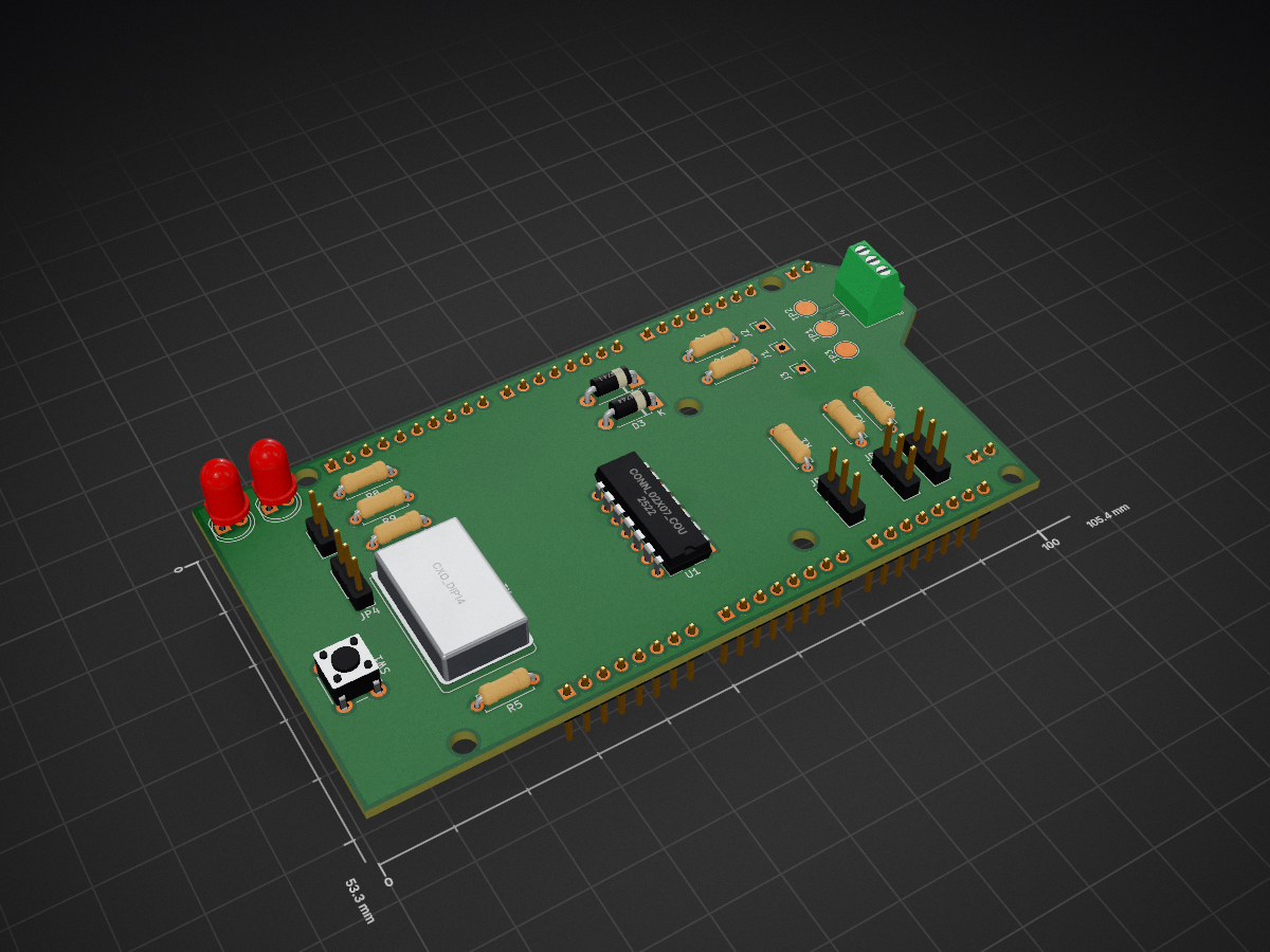
 Moddler/CCD-Arduino-Mega4
An Arduino mega shield for interfacing with Chrysler's legacy CCD databus.
CCD Arduino Mega is an open-source printed circuit board by Moddler, from the Moddler/CCD-Arduino-Mega repository on GitHub, published under the MIT licence. It is a 2-layer board of 105.4 × 53.3 mm with 36 parts on 62 nets, routed with 113 tracks and 0 vias.
Its parts include 13 connectors, 9 resistors, 4 diodes, 1 IC and 1 switch.
! Work in Progress - Entirely untested !
An Arduino mega shield for interfacing with Chrysler's legacy CCD databus.
This project is a shield for the Arduino Mega 2560. It is designed to hold all the parts necessary to interface with Chrysler's legacy databus CCD, utilized in Chrysler vehicles from the late 80s to late 90s.
The shield can hold a CCD chip in PDIP 14 formfactor, which enables the communication between Arduino Mega and a CCD-databus. For this scenario a quartz oscillator is needed on the PCB.
Known variants/labels of this chip are:
Intersil CDP68HC68S1E (PDIP 14)
Harris 4374040 (PDIP 14)
Harris 306846 (PDIP 14)
Signetics 4517535 (PDIP 14)
Intersil CDP68HC68S1M (SOIC 20)
Philips 4651148 (SOIC 20)
Philips 04833637 (SOIC 20)
Signetics 4632650 (SOIC 20)
Additionally, this board can hold the CCDBusTranceiver_v300 from https://github.com/laszlodaniel/CCDBusTransceiver No oscillator is needed here, this is the preferred method.
There are three jumpers available for setting bus termination and bus bias voltage.
A pushbutton and two LEDs are also available for whatever one could use them.
There is no specific software available at this point.
This device is meant to be able to tinker with ECUs/BCMs/EATX-Controllers etc. on a testbench, without having to worry about the circuits around the CCD interfacing-chip.
It probably can also be used to sniff CCD messages in a vehicle, or trigger diagnostic commands. It is not a full blown diagnostic device and will never be, since it is missing some other features Chrysler used in old vehicles.
The board is powered via the USB connection of the Arduino, and also enables the serial communication with a serial console or program. The simplest way to get started is to use the serial passthrough example sketch and set the baud rate communication to the chip to 7812,5 Baud (CCD bus baud speed).
Related and highly respected work:
Juha Niinikoski http://www.kolumbus.fi/juha.niinikoski/CCD_bus/ccd_display.htm
Boundary Condition / László Dániel https://chryslerccdsci.wordpress.com https://github.com/laszlodaniel/ChryslerCCDSCIScanner https://github.com/laszlodaniel/CCDLibrary https://github.com/laszlodaniel/CCDBusTransceiver
Geoff / moparchem.com / Ladybug / Dcal
ShelGame at turbo-mopar.com http://www.turbo-mopar.com/forums/member.php?141-ShelGame
wowzer at turbo-mopar.com http://www.turbo-mopar.com/forums/member.php?1068-wowzer
majekw https://github.com/majekw/sigrok-ccd-pd
xerootg https://github.com/xerootg
NickInTimeDesign https://nickintimedesign.com
| Qty | Value | Footprint | References |
|---|---|---|---|
| 2 | 10Ω | Resistor_THT:R_Axial_DIN0207_L6.3mm_D2.5mm_P7.62mm_Horizontal | R6, R7 |
| 2 | 13kΩ | Resistor_THT:R_Axial_DIN0207_L6.3mm_D2.5mm_P7.62mm_Horizontal | R2, R3 |
| 2 | 1N4744 | Diode_THT:D_DO-41_SOD81_P7.62mm_Horizontal | D3, D4 |
| 2 | 220Ω | Resistor_THT:R_Axial_DIN0207_L6.3mm_D2.5mm_P7.62mm_Horizontal | R8, R9 |
| 2 | ANALOG | Connector_PinHeader_2.54mm:PinHeader_1x08_P2.54mm_Vertical | J7, J8 |
| 2 | BIAS | Connector_PinHeader_2.54mm:PinHeader_1x03_P2.54mm_Vertical | JP2, JP3 |
| 2 | LED | LED_THT:LED_D5.0mm | D1, D2 |
| 1 | +5V | Connector_PinHeader_2.54mm:PinHeader_2x01_P2.54mm_Vertical | J10 |
| 1 | 100kΩ | Resistor_THT:R_Axial_DIN0207_L6.3mm_D2.5mm_P7.62mm_Horizontal | R4 |
| 1 | 120kΩ | Resistor_THT:R_Axial_DIN0207_L6.3mm_D2.5mm_P7.62mm_Horizontal | R1 |
| 1 | Button | Connector_PinHeader_2.54mm:PinHeader_1x02_P2.54mm_Vertical | J5 |
| 1 | CCD+ | Connector_PinSocket_2.54mm:PinSocket_1x01_P2.54mm_Vertical | J1 |
| 1 | CCD+ | TestPoint:TestPoint_Pad_D3.0mm | TP1 |
| 1 | CCD- | Connector_PinSocket_2.54mm:PinSocket_1x01_P2.54mm_Vertical | J2 |
| 1 | CCD- | TestPoint:TestPoint_Pad_D3.0mm | TP2 |
| 1 | CCD-BUS | TerminalBlock_Phoenix:TerminalBlock_Phoenix_MPT-0,5-3-2.54_1x03_P2.54mm_Horizontal | J4 |
| 1 | COMMUNICATION | Connector_PinHeader_2.54mm:PinHeader_1x08_P2.54mm_Vertical | J13 |
| 1 | CXO_DIP14 | Oscillator:Oscillator_DIP-14 | X1 |
| 1 | Conn_02x07_Counter_Clockwise | Package_DIP:DIP-14_W7.62mm | U1 |
| 1 | GND | Connector_PinHeader_2.54mm:PinHeader_2x01_P2.54mm_Vertical | J9 |
| 1 | Ground | TestPoint:TestPoint_Pad_D3.0mm | TP3 |
| 1 | Ground | Connector_PinSocket_2.54mm:PinSocket_1x01_P2.54mm_Vertical | J3 |
| 1 | Jumper_NC_Dual | Connector_PinHeader_2.54mm:PinHeader_1x03_P2.54mm_Vertical | JP4 |
| 1 | POWER | Connector_PinHeader_2.54mm:PinHeader_1x08_P2.54mm_Vertical | J6 |
| 1 | PWM | Connector_PinHeader_2.54mm:PinHeader_1x08_P2.54mm_Vertical | J12 |
| 1 | PWM | Connector_PinHeader_2.54mm:PinHeader_1x10_P2.54mm_Vertical | J11 |
| 1 | R | Resistor_THT:R_Axial_DIN0207_L6.3mm_D2.5mm_P7.62mm_Horizontal | R5 |
| 1 | SW_Push | Button_Switch_THT:SW_PUSH_6mm | SW1 |
| 1 | Termination | Connector_PinHeader_2.54mm:PinHeader_1x03_P2.54mm_Vertical | JP1 |
hoglet67/RGBtoHDMI
Bare-metal Raspberry Pi project that provides pixel-perfect sampling of Retro Computer RGB/YUV video and conversion to HDMI

hackclub/OnBoard
💡 Join 1,000 teenagers and make your first PCB with a $100 grant!


tardate/LittleArduinoProjects
a collection of "Little Electronic & Arduino Projects", most involving electronics or an Arduino in one way or another!


Neumi/open_echo
Open Source echo sounder / depth sounder / SONAR for bathymetry and research. Arduino based and compatible.


It measures 105.4 × 53.3 mm and has 2 copper layers, 1.6 mm thick.
36 parts. The full list of its parts is on this page, with links to each part's symbol and footprint where PCBKit's library has them.
From the Moddler/CCD-Arduino-Mega repository on GitHub, at the commit this page was made from: the board is KiCad/CCD-Arduino-Mega.kicad_pcb and its schematic KiCad/CCD-Arduino-Mega.kicad_sch. PCBKit opens the board in the browser, with nothing to install.
Its repository publishes it under the MIT licence: you may reuse it on that licence's terms (keep the author's notice, and for a copyleft licence share your changes alike).