Skip to the content
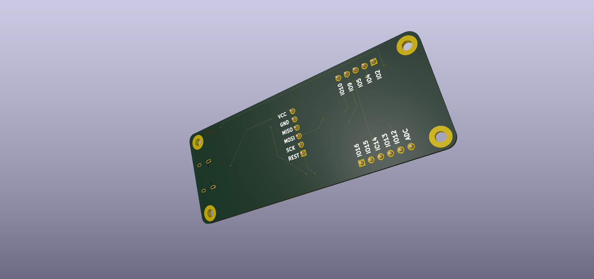
2 layers79 × 30.5 mmEsp 8266 dev board, the printed circuit board in 3D

Esp 8266 dev board

Mo3tasemO/PCB_Designs

A custom-designed, high-performance development board based on the ESP-12E (ESP8266) module. This board features a modern USB-C interface and is designed for seamless prototyping with integrated power regulation and…

Size
79 × 30.5 mm
Copper layers
2
Thickness
1.6 mm
Parts
28
Nets
49
Pads
119
Tracks, vias
201, 15
Pours
1
Routed
Yes
KiCad
KiCad 9.0 (file 20241229)
Created
3 Feb 2026
Updated
24 Aug 2026

Overview

Esp 8266 dev board is an open-source printed circuit board by Mo3tasemO, from the Mo3tasemO/PCB_Designs repository on GitHub. It is a 2-layer board of 79 × 30.5 mm with 28 parts on 49 nets, routed with 201 tracks and 15 vias.

It is built around the CH340C, AMS1117-3.3 and BZV55B3V3. Its parts include 7 resistors, 5 capacitors, 4 connectors, 3 ICs and 3 diodes. It belongs with the microcontroller boards boards and the ESP8266 boards of this library.

Main components

3

README

ESP 8266_Dev_Board/ESP 8266_Dev_Board/README.md

DEV_Board_By_Mo3 (ESP8266-12E)

A custom-designed, high-performance development board based on the ESP-12E (ESP8266) module. This board features a modern USB-C interface and is designed for seamless prototyping with integrated power regulation and USB-to-TTL conversion.


🚀 Key Features

  • Core Microcontroller: ESP8266-12E module with integrated PCB antenna.
  • Modern Interface: USB-C 16-pin receptacle for power and programming.
  • Stable Power: AMS1117-3.3V LDO regulator providing consistent 3.3V power from the 5V USB input.
  • USB-to-Serial: Integrated CH340C bridge chip for plug-and-play serial communication.
  • Protection: Includes a BZW55B3V3 Zener diode and decoupling capacitors for voltage stability and ESD protection.
  • Manual Controls: Dedicated Flash (DTR/RTS logic) and Reset (SW_SPST) buttons for easy bootloader access.

🛠 Hardware Architecture

The board is logically divided into four main sections as defined in the schematics:

SectionComponentsPurpose
SourceAMS1117-3.3, BZW55B3V3, C1, C3Voltage regulation and power filtering.
USBUSB-C 16P, D2 Diode, C6Power input and basic surge protection.
USB to TTLCH340C, C4, C5, R4, R5Bridge between PC USB and ESP8266 UART.
ESP8266ESP-12E, Reset/Flash Switch, I/O HeadersMain processing, GPIO breakout, and boot mode selection.

📐 Pinout & Connectivity

The board breaks out all essential GPIOs via two main headers:

  • Header J3: GPIO12, GPIO13, GPIO14, GPIO15, GPIO16, and GND.
  • Header J4: RESET, SCK, MOSI, MISO, and GND.
  • Header J5: ADC and various ID pins for expanded peripheral support.

🖥️ Setup and Programming

  1. Driver Installation: Ensure the CH340 drivers are installed on your computer.
  2. Arduino IDE Configuration: * Add the ESP8266 board URL to your preferences.
    • Select "NodeMCU 1.0 (ESP-12E Module)" or "Generic ESP8266 Module".
  3. Flashing: Use the USB-C cable to connect to your PC. The board features an auto-reset circuit (DTR/RTS) for automatic flashing, but manual buttons are available if needed.

🖼️ Gallery

2D Layout & Routing
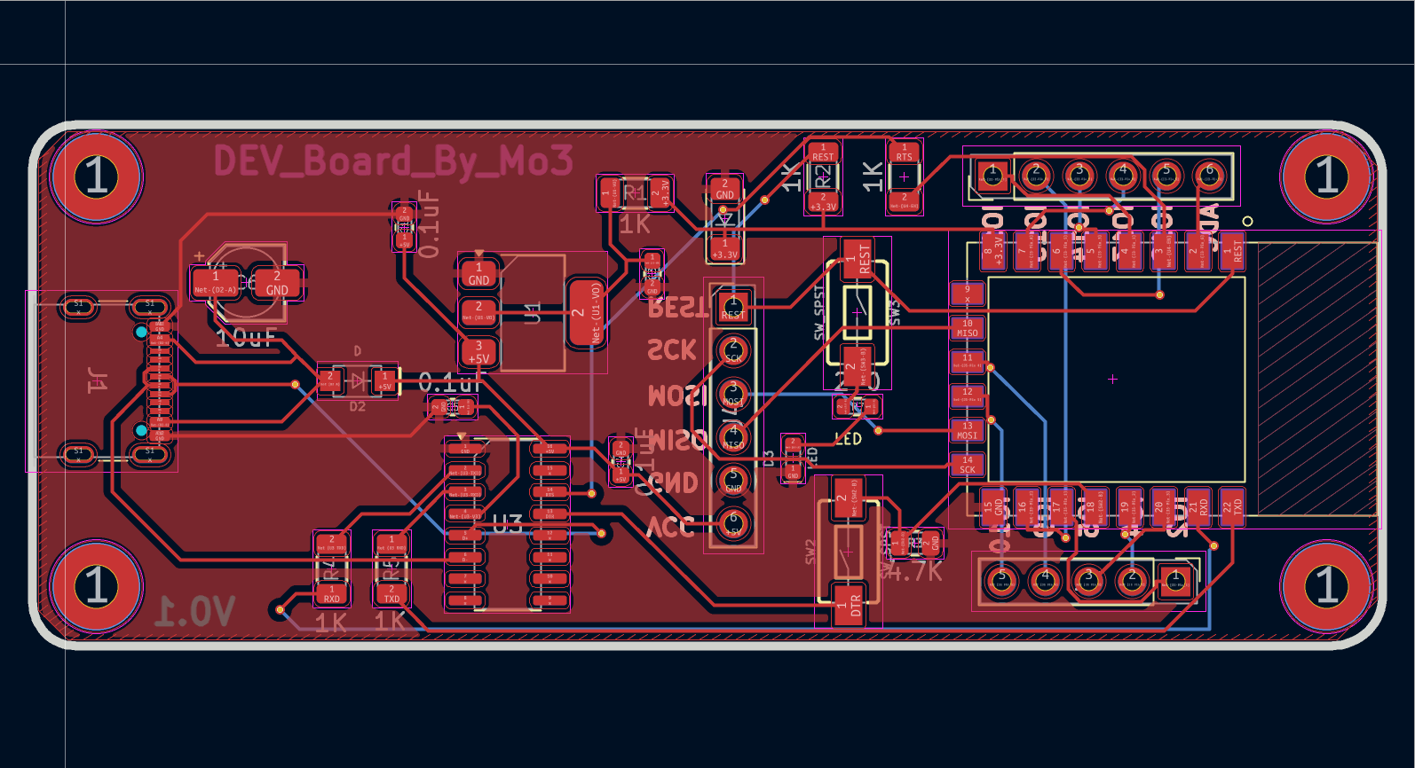
PCB Layout
Double-layer design with optimized ground pours for RF stability.

3D Render
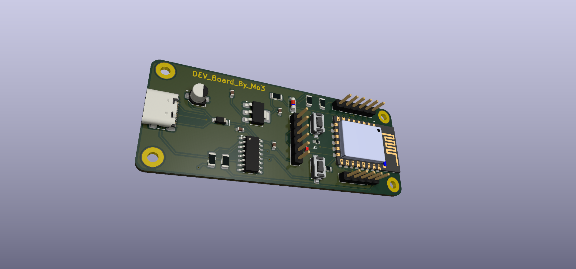
3D Render 3D Render Fully assembled view showing component placement and compact form factor.


📜 License

This project is open-source. Feel free to use, modify, and distribute it for your own IoT applications.

Parts

28
QtyValueFootprintReferences
51KResistor_SMD:R_1206_3216MetricR1, R2, R4, R5, R6
40.1uFCapacitor_SMD:C_0603_1608MetricC1, C3, C4, C5
2Conn_01x06_PinConnector_PinHeader_2.54mm:PinHeader_1x06_P2.54mm_VerticalJ3, J4
2SW_SPSTSparkFun-Switch:Push_SMD_6x3.5mmSW2, SW3
110uFCapacitor_SMD:CP_Elec_4x4.5C6
1270Resistor_SMD:R_0603_1608MetricR7
14.7KResistor_SMD:R_0805_2012MetricR3
1AMS1117-3.3Package_TO_SOT_SMD:SOT-223-3_TabPin2U1
1BZV55B3V3Diode_SMD:D_MiniMELFD1
1CH340CPackage_SO:SOIC-16_3.9x9.9mm_P1.27mmU3
1Conn_01x05_PinConnector_PinHeader_2.54mm:PinHeader_1x05_P2.54mm_VerticalJ5
1DSparkFun-Semiconductor-Standard:SOD-123D2
1ESP8266-12E_ESP-12EESP8266-12E_ESP-12E:XCVR_ESP8266-12E_ESP-12EU4
1LEDSparkFun-LED:LED_0603_1608Metric_RedD3
1USB_C_Receptacle_USB2.0_16PConnector_USB:USB_C_Receptacle_GCT_USB4105-xx-A_16P_TopMnt_HorizontalJ1

The 24 most common of 28 parts.

More from Mo3tasemO/PCB_Designs

3
  • 2 layers89 × 59.1 mmFunction Generator, the printed circuit board in 3D

    Function Generator

    Mo3tasemO/PCB_Designs

    A custom-designed, high-performance development board based on the ESP-12E (ESP8266) module. This board features a modern USB-C interface and is designed for seamless prototyping with integrated power regulation and…

    28 parts
  • 2 layers140 × 80 mmDual Force Plate, the printed circuit board in 3D

    Dual Force Plate

    Mo3tasemO/PCB_Designs

    A custom-designed, high-performance development board based on the ESP-12E (ESP8266) module. This board features a modern USB-C interface and is designed for seamless prototyping with integrated power regulation and…

    26 parts
  • 2 layers32.3 × 55.8 mmBreadboard Power Supply, the printed circuit board in 3D

    Breadboard Power Supply

    Mo3tasemO/PCB_Designs

    A custom-designed, high-performance development board based on the ESP-12E (ESP8266) module. This board features a modern USB-C interface and is designed for seamless prototyping with integrated power regulation and…

    19 parts

Similar boards

  • 4 layers85.1 × 53.3 mmEsp32-faerfly V2.0, the printed circuit board in 3D

    Esp32-faerfly V2.0

    low-poly-studio/esp32-faerfly

    Imogen Wren Business Card Light Show PCB

    103 parts5
  • 2 layers162.8 × 99.9 mmPSU, the printed circuit board in 3D

    PSU

    Sakib-Ansari/Linear_Programmable_Power_Supply

    This repository contains the complete KiCad project for a multi-board linear programmable bench power supply. The design is organized into separate PCBs, including the Power Board, Control Board, Front Panel, Output…

    133 partsMIT
  • 2 layers108.2 × 124.9 mmSBC, the printed circuit board in 3D

    SBC

    ahmedsiddyq/mine_sweeper

    A software implementation of the classic Minesweeper game.

    373 parts
  • 2 layers76.2 × 50.8 mmFrequencySensor, the printed circuit board in 3D

    FrequencySensor

    manthanand/SeniorDesign

    Senior Design Project

    6 parts4
  • 2 layers94.5 × 228 mmRampedFetCoil, the printed circuit board in 3D

    RampedFetCoil

    flyingperson23/RampedFetCoil

    157 parts2
  • 2 layers100 × 50 mmCarga Electronica, the printed circuit board in 3D

    Carga Electronica

    kr4fty/Carga-Electronica-STM32

    Desarrollo de un Sistema de Control PID para una Carga Electrónica utilizando un STM32

    49 parts1
  • 2 layers83.8 × 86.4 mmPCB Schematics, the printed circuit board in 3D

    PCB Schematics

    AlexJwll/PCB_Schematics

    21 parts
  • 2 layers133.5 × 78 mmCaculateur, the printed circuit board in 3D

    Caculateur

    Augustin-29/Calculateur_TOIT_206CC

    Ce projet open-source consiste en la rétro-ingénierie et la conception d'un calculateur de remplacement sur mesure pour la gestion du toit escamotable d'une Peugeot 206 CC.

    110 parts

Questions

How big is the Esp 8266 dev board PCB?

It measures 79 × 30.5 mm and has 2 copper layers, 1.6 mm thick.

What parts does the Esp 8266 dev board use?

28 parts, built around the CH340C, AMS1117-3.3 and BZV55B3V3. The full list of its parts is on this page, with links to each part's symbol and footprint where PCBKit's library has them.

Where can I download the Esp 8266 dev board KiCad files?

From the Mo3tasemO/PCB_Designs repository on GitHub, at the commit this page was made from: the board is ESP 8266_Dev_Board/ESP 8266_Dev_Board/esp 8266 dev board.kicad_pcb and its schematic Breadboard_Power_Supply/Breadboard_Power_Supply.kicad_sch. PCBKit opens the board in the browser, with nothing to install.

Can I use the Esp 8266 dev board design in my own project?

Its repository states no licence, so its author keeps all rights: ask Mo3tasemO before reusing the design.