
4 layers95 × 95 mm
Cube motherboard
willem-pennings/balancing-cube
A cube that balances itself in a corner or edge using reaction wheels
52 parts1.1kGPL-3.0
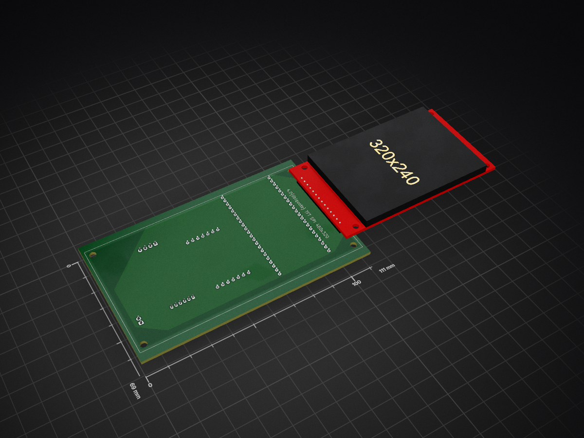
 Minall13/WiFi_Radio_Project2
ESP32-S3 Wi-Fi internet radio with touchscreen UI, dual-mono I²S audio, custom PCB and 3D-printable enclosure.
Internet Radio is an open-source printed circuit board by Minall13, from the Minall13/WiFi_Radio_Project repository on GitHub. It is a 2-layer board of 111 × 69 mm with 9 parts on 51 nets, routed with 92 tracks and 0 vias.
It is built around the ESP32-S3-DEVKITC-1-N8. Its parts include 4 connectors, 3 ICs and 2 resistors. It belongs with the radio and wireless boards and the ESP32 boards of this library.
A standalone touchscreen Internet radio built around the ESP32-S3, with a curated UK station library, live programme metadata, custom carrier PCB and a fully 3D-printed enclosure.
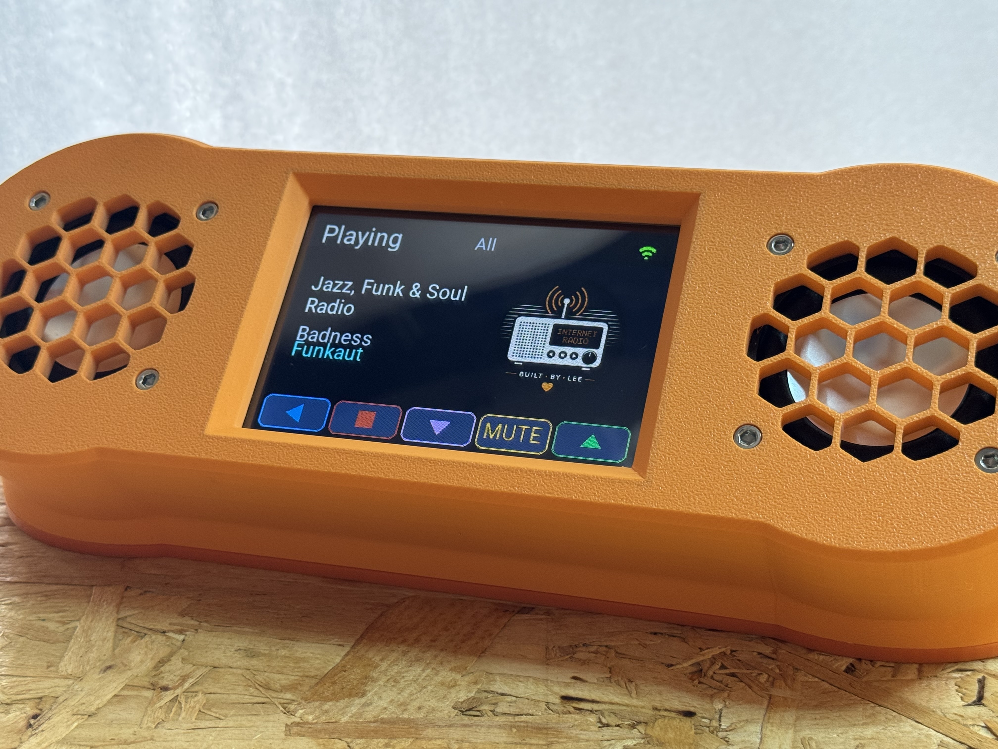
The Wi-Fi Radio Project was developed from an initial ESP32 prototype into a complete self-contained radio. The hardware, firmware, user interface, station catalogue, artwork pipeline, PCB and enclosure have all been developed specifically for the project.
The finished radio is designed to behave as an appliance: switch it on, select a station and listen.
The radio uses a purpose-built touchscreen interface rather than a generic ESP32 menu system.
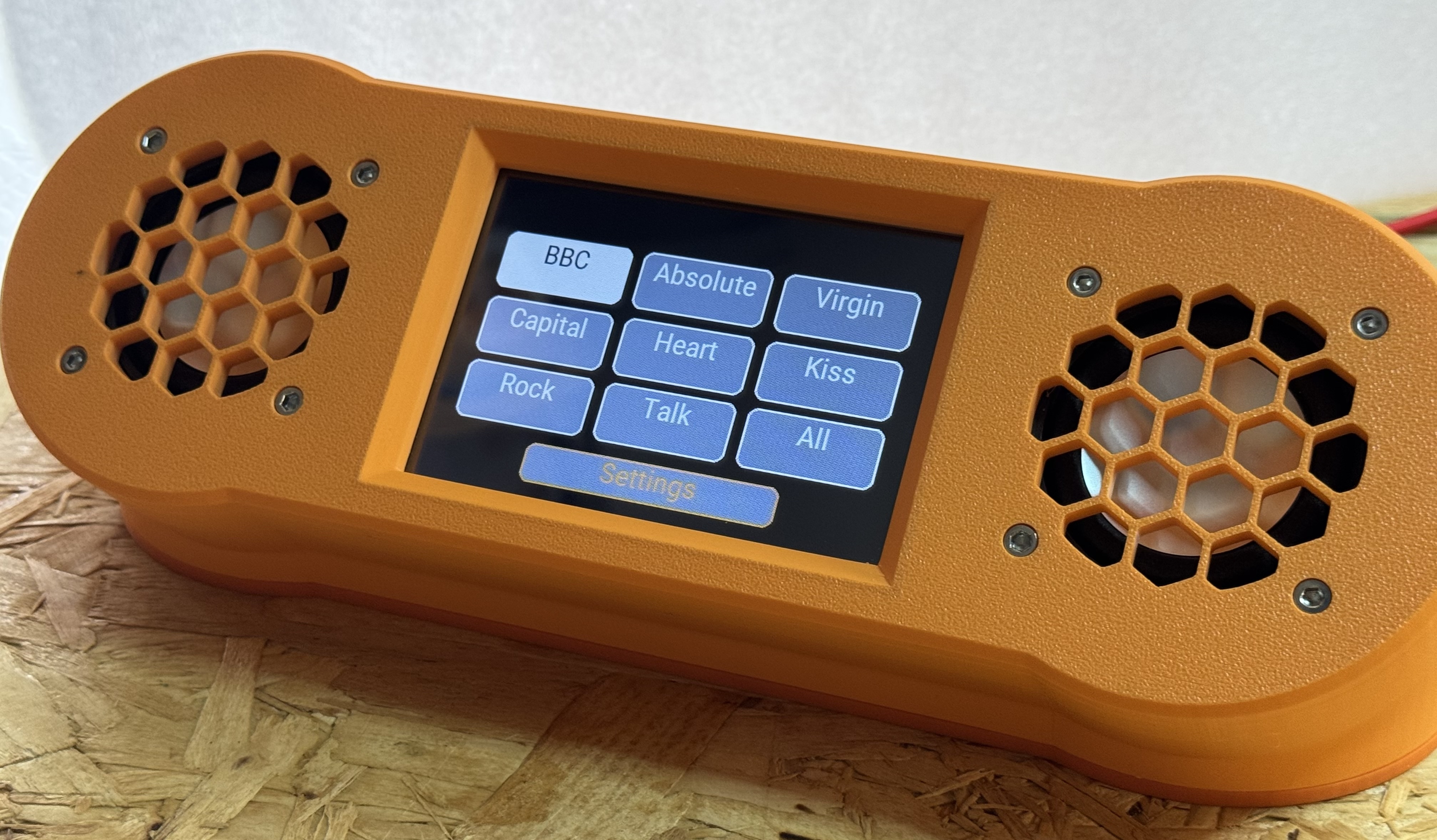
Stations are organised into simple groups such as BBC, Absolute, Virgin, Capital, Heart, Kiss, Rock and Talk, with an All option providing access to the complete catalogue.
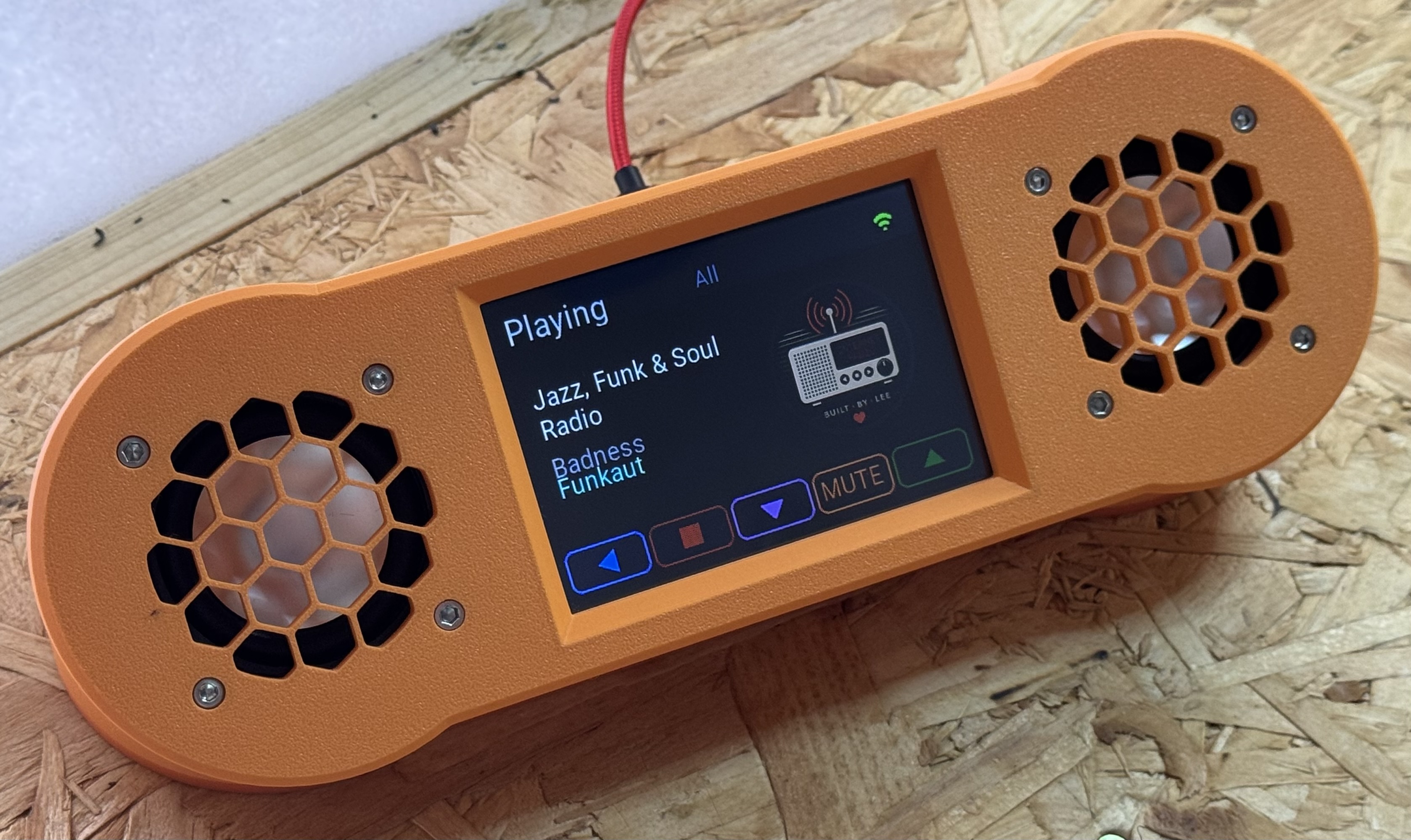
The Player screen displays the current station, programme or track information and station artwork, together with controls for navigation, stop, volume and mute.
The startup sequence initialises the filesystem, connects to Wi-Fi, prepares BBC programme information and starts the audio subsystem before presenting the radio for use.
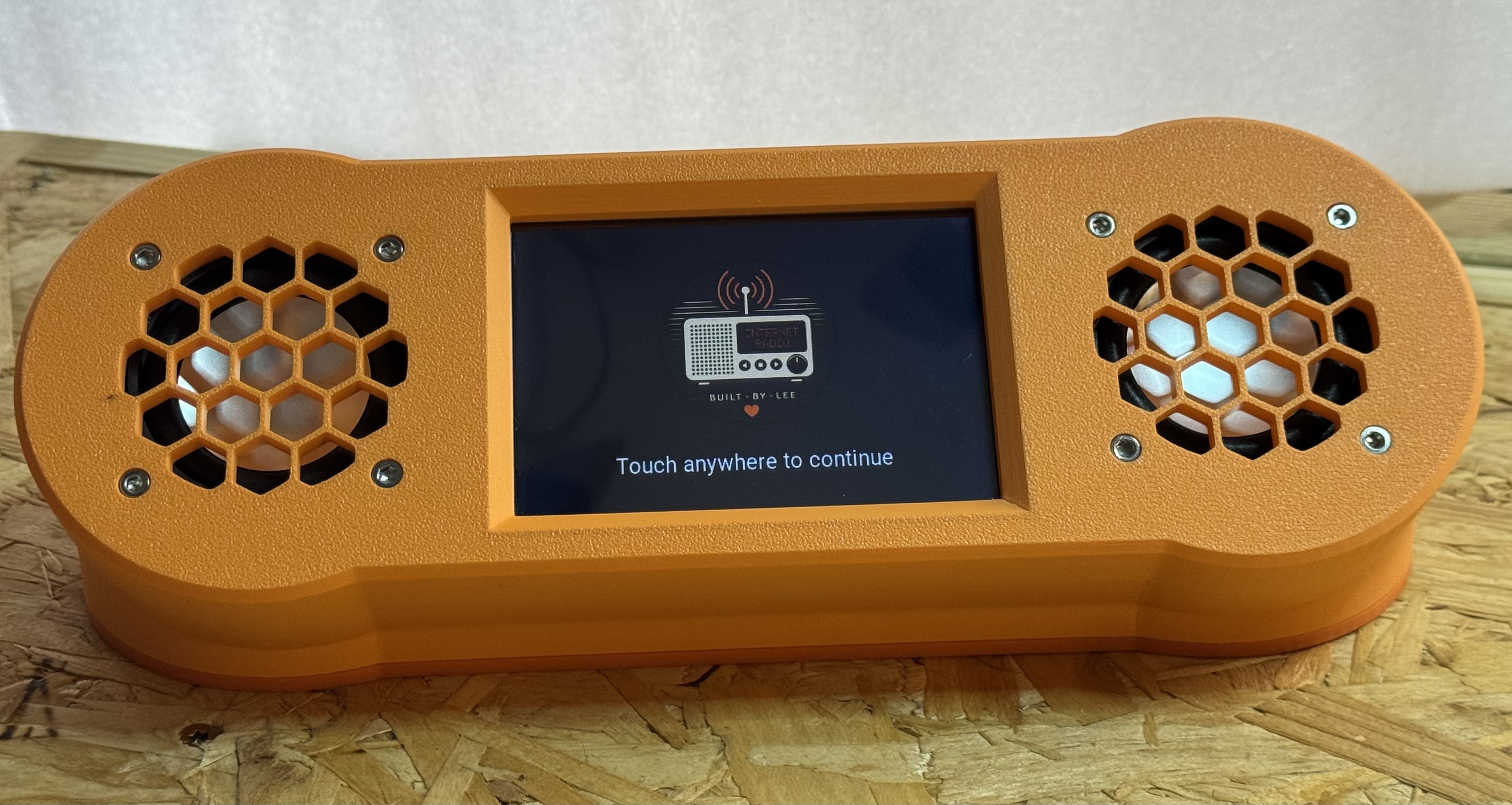
The radio is based around an ESP32-S3 DevKitC-1 N16R8:
ILI9481_DRIVERDual-mono audio is provided by:
A custom KiCad-designed carrier PCB connects the ESP32-S3, display, audio modules, power switching and external USB-C connection.
The PCB was designed specifically for the finished radio and manufactured as part of the project.
The proven Rev A PCB can be ordered directly from the Wi-Fi Radio Project page on PCBWay.
The rear-panel USB-C connection provides both normal 5 V power and access to the ESP32-S3 USB interface, allowing firmware to be uploaded without dismantling the radio.
PCB design files and manufacturing Gerbers are provided in the Hardware/ directory.
The enclosure is fully 3D printed and consists of three principal components:
STL files are provided in this repository for slicer-independent printing.
A Bambu Studio 3MF project, including the complete assembly and individual printable components, is available on MakerWorld.
The files are located in:
3D_Files/
A complete parts list for one radio is provided in:
The BOM includes quantities and example sources for the components used in the original build.
Equivalent components may be used where their electrical and mechanical specifications are compatible.
The firmware is divided into independent subsystems with clearly defined responsibilities.
Station Library Builder
        │
        ▼
LittleFS Catalogue
        │
        ▼
Station Provider
        │
        ▼
User Interface
        │
        ▼
Player
        │
        ├───────────────┐
        ▼               ▼
Audio Engine     BBC Metadata
        │
        ▼
I²S Audio
        │
        ▼
2 × MAX98357A
This separation keeps the user interface, station data, metadata handling and audio playback largely independent of one another.
More detailed design information is available in the docs/ directory.
Rather than querying an Internet radio directory every time the radio starts, the project uses a curated UK station catalogue generated offline.
The Station Library Builder:
The ESP32 therefore operates from its own local catalogue during normal use.
This makes the radio independent of a live station-directory service while it is operating.
Commercial stations primarily use ICY metadata supplied by their audio streams.
BBC stations are handled separately using BBC programme metadata, allowing the Player screen to display the programme currently being broadcast.
Station artwork is stored as PNG images in LittleFS and displayed on the Player screen.
The artwork pipeline can obtain station artwork, apply curated replacements where necessary, generate appropriately sized images and provide default artwork for stations without suitable source material.
Station names, logos and other third-party branding remain the property of their respective owners. Third-party station artwork is not intended to imply affiliation with or endorsement of this project.
WiFi_Radio_Project/
│
├── 3D_Files/                       3D-printable enclosure files
├── Hardware/                       KiCad PCB design and manufacturing files
├── data/                           Station catalogue and runtime assets
│   ├── branding/
│   ├── catalogues/
│   ├── fonts/
│   ├── icons/
│   └── logos/
├── docs/                           Project documentation
├── images/                         Documentation images
├── tools/                          Build and asset-generation utilities
│   ├── Icon_Builder/
│   └── Station_Library_Builder/
│
├── WiFi_Radio_Project.ino	        Main Arduino sketch
├── partitions.csv                  ESP32 flash partition layout
├── deploy                          LittleFS deployment helper
├── BOM.md                          Bill of materials
└── README.md
The remaining numbered .ino files in the project root contain the supporting firmware modules.
The repository contains the principal resources required to reproduce the project:
The project was developed and tested using the specific hardware listed in the BOM. Substituting components may require changes to the PCB, enclosure, firmware configuration or pin assignments.
Version 1.0.1
The Wi-Fi Radio Project has reached its first complete hardware and software release.
The v1.0.1 system includes:
The radio has been assembled and tested as a complete standalone unit.
Additional technical documentation is available in the docs/ directory, covering subjects including:
This project uses a number of third-party open-source libraries, hardware modules and Internet services.
Radio station names and trademarks belong to their respective owners.
Availability and format of Internet radio streams and external metadata services can change independently of this project.
The Wi-Fi Radio Project uses a mixed licensing model.
Original project software is licensed under the PolyForm Noncommercial License 1.0.0.
Original hardware designs, PCB files, 3D-printable models, documentation and project photographs are licensed under the Creative Commons Attribution-NonCommercial 4.0 International (CC BY-NC 4.0) licence.
These licences permit personal, non-commercial use, modification and redistribution subject to their respective terms and attribution requirements. Commercial use of the original project material is not permitted without separate permission from the copyright holder.
Third-party components and assets remain subject to their own licences.
See LICENSE.md for the complete licensing details and attribution requirements.
| Qty | Value | Footprint | References |
|---|---|---|---|
| 2 | 5K1 | Resistor_SMD:R_0603_1608Metric | R1, R2 |
| 2 | MY_MAX98357A | Internet_Radio:MY_MAX98357A_PNG | U3, U4 |
| 1 | ESP32-S3-DevKitC | Internet_Radio:ESP32-S3-DevKitC_PNG | U1 |
| 1 | POWER SW | Connector_JST:JST_XH_B2B-XH-A_1x02_P2.50mm_Vertical | J5 |
| 1 | TFT_4_TOUCH_SPI_480x320 | Internet_Radio:TFT_4_TOUCH_SPI_480x320_PNG | J1 |
| 1 | USB ESP32 | Connector_JST:JST_XH_B4B-XH-A_1x04_P2.50mm_Vertical | J4 |
| 1 | USB PANEL | Connector_JST:JST_PH_B6B-PH-K_1x06_P2.00mm_Vertical | J2 |
willem-pennings/balancing-cube
A cube that balances itself in a corner or edge using reaction wheels

jazzmonger/Traeger-PID-Controller
Traeger Smoker/Grill Controller based on an

ohasanov-hbrw/tribit32-advanced
A tri-microcontroller, overengineered GameBoy Advance clone. More value was given to the controls and the exterior look, which is cool!


FIPATECH/CDFR26_PAMI
Open source firmware and PCB for a differential mobile robot (PAMI) based on ESP32-S3 - Coupe de France de Robotique

dnhutchins/ETC_Express_Reverse_Eng
The ultimate goal of this work is to develop an interface to use the control surface from a legacy ETC Express 24/48 lighting controller as a modern EOSNomad compatible programming and fader wing.

heckler/esphome-device-configs
Configuration definitions for local ESPHome files
It measures 111 × 69 mm and has 2 copper layers, 1.6 mm thick.
9 parts, built around the ESP32-S3-DEVKITC-1-N8. The full list of its parts is on this page, with links to each part's symbol and footprint where PCBKit's library has them.
From the Minall13/WiFi_Radio_Project repository on GitHub, at the commit this page was made from: the board is Hardware/Internet_Radio.kicad_pcb and its schematic Hardware/Internet_Radio.kicad_sch. PCBKit opens the board in the browser, with nothing to install.
Its repository states no licence, so its author keeps all rights: ask Minall13 before reusing the design.