Board kecil yang ditumpuk di atas PCB utama (konsep v17, 03/11/2026): OLED 0,96 inci di socket di tengah, 5 tombol 6×6 mengapit untuk menu OLED (kiri: atas, bawah; kanan: kembali, OK, lanjut).
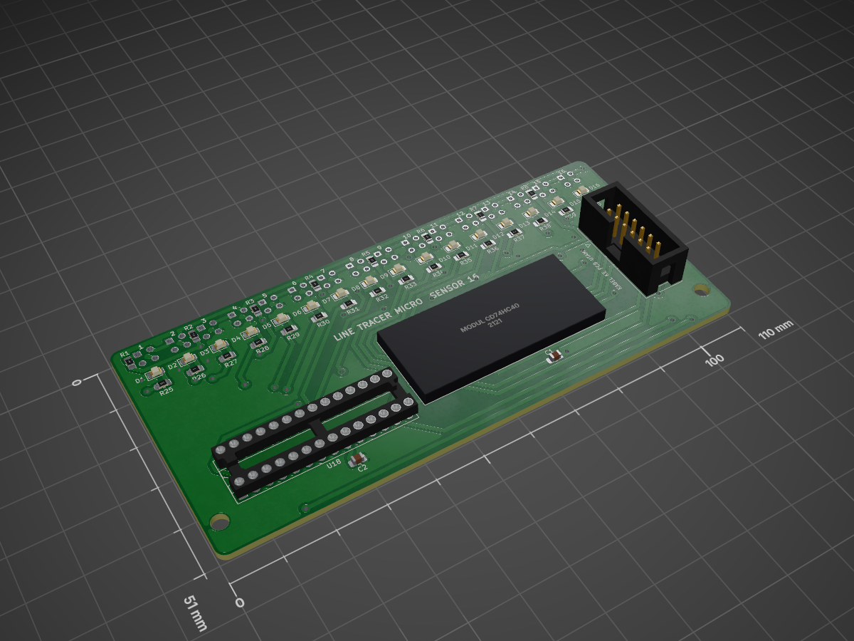
Ltm sensor is an open-source printed circuit board by Mervs111, from the Mervs111/Line-Follower-Racer repository on GitHub. It is a 2-layer board of 110 × 51 mm with 82 parts on 81 nets, routed with 642 tracks and 56 vias.
It is built around the MCP23017-E/SS and AO3400. Its parts include 42 resistors, 18 ICs, 16 diodes, 2 capacitors and 1 transistor. It belongs with the sensors and measurement boards of this library.
Board kecil yang ditumpuk di atas PCB utama (konsep v17, 03/11/2026): OLED 0,96 inci di socket di tengah, 5 tombol
6×6 mengapit untuk menu OLED (kiri: atas, bawah; kanan: kembali, OK, lanjut). Ukuran konsep 46 × 32 mm, PCB jadi 46 × 36 mm (ditambah lubang M2).
File
Isi
board-interface.kicad_pro
salinan setting PCB utama (aturan cetak, net class)
board-interface.kicad_sch
skematik rev A dari hardware/tools/gen_sch_interface.py, 13 komponen, ERC 0. PDF: board-interface-skematik.pdf
Tangga resistor: tombol k menghubungkan BTN (GPIO34) ke GND lewat Rk; pull-up 10k (R5) ada di PCB utama.
Tombol
Rk
Tegangan BTN
SW1 Atas
1k
0,30 V
SW2 Bawah
3,9k
0,93 V
SW3 Kembali
8,2k
1,49 V
SW4 OK
18k
2,12 V
SW5 Lanjut
39k
2,63 V
tidak ditekan
–
3,3 V
Hanya satu tombol terbaca dalam satu waktu (cukup untuk menu). C1 100 nF di BTN meredam derau.
J1 = header 1×6 (urutan sama dengan J6 PCB utama: +3V3, GND, SDA, SCL, BTN, AUX tidak dipakai). Jarak antar board
±16 mm (atas PCB utama z 16,6 → bawah board interface z 33). Socket J6 8,5 mm + header biasa (6 mm masuk) tidak
sampai, jadi perlu header pin panjang atau spacer. Cara pasang board ini (dudukan) belum diputuskan.
PCB rev A (04/11/2026)
Dibuat oleh hardware/tools/gen_pcb_interface.py (penempatan, silkscreen, pour) + hardware/tools/autoroute/sisa.py
(routing, GND lewat pour). Render: render-atas.png, render-bawah.png.
46 × 36 mm (x robot −27..19, y 43..79), sudut R2, 4 lubang M2 di pojok (x −24,5 / 16,5, y 45,5 / 76,5),
untuk dudukan apa pun yang dipilih nanti (jembatan 3D print ke lubang M3 PCB utama, spacer, atau cover).
OLED di socket J2 (tengah atas; modulnya 27,3 × 27,8 mm menutupi tangga resistor). Tombol: kiri ATAS/BAWAH, kanan
KEMBALI/OK/LANJUT. R1/R2 di kiri, R3–R5 di kanan, dekat tombolnya.
J1 dipasang di sisi bawah (menghadap PCB utama). Pin 1–6 di x −5,6 … 7,1, y 67,5, sama persis dengan J6 PCB
utama (dicek dari kedua file .kicad_pcb).
Routing 2 layer tanpa via, GND pour F.Cu + B.Cu. DRC: 0 error, 0 warning, 0 unconnected, cocok dengan
skematik. Aturan tambahan board-interface.kicad_dru: courtyard tombol 6×6 dan lubang M2 boleh bersinggungan
(badan tombol berjarak 3 mm, tembaga ke lubang ≥ 1,1 mm).
Board kecil yang ditumpuk di atas PCB utama (konsep v17, 03/11/2026): OLED 0,96 inci di socket di tengah, 5 tombol 6×6 mengapit untuk menu OLED (kiri: atas, bawah; kanan: kembali, OK, lanjut).
Board kecil yang ditumpuk di atas PCB utama (konsep v17, 03/11/2026): OLED 0,96 inci di socket di tengah, 5 tombol 6×6 mengapit untuk menu OLED (kiri: atas, bawah; kanan: kembali, OK, lanjut).
Board kecil yang ditumpuk di atas PCB utama (konsep v17, 03/11/2026): OLED 0,96 inci di socket di tengah, 5 tombol 6×6 mengapit untuk menu OLED (kiri: atas, bawah; kanan: kembali, OK, lanjut).
Board kecil yang ditumpuk di atas PCB utama (konsep v17, 03/11/2026): OLED 0,96 inci di socket di tengah, 5 tombol 6×6 mengapit untuk menu OLED (kiri: atas, bawah; kanan: kembali, OK, lanjut).
Standalone LoRa-based real-time off-grid relative GPS navigation for group of up to 5 people. Improved version of LRNS Eleph
143 parts16GPL-3.0
Questions
How big is the Ltm sensor PCB?
It measures 110 × 51 mm and has 2 copper layers, 1.6 mm thick.
What parts does the Ltm sensor use?
82 parts, built around the MCP23017-E/SS and AO3400. The full list of its parts is on this page, with links to each part's symbol and footprint where PCBKit's library has them.
Where can I download the Ltm sensor KiCad files?
From the Mervs111/Line-Follower-Racer repository on GitHub, at the commit this page was made from: the board is arsip/hardware/ltm-sensor/ltm-sensor.kicad_pcb and its schematic arsip/hardware/ltm-sensor/ltm-sensor.kicad_sch. PCBKit opens the board in the browser, with nothing to install.
Can I use the Ltm sensor design in my own project?
Its repository states no licence, so its author keeps all rights: ask Mervs111 before reusing the design.