2 layers
Nrf bga
github-linguist/linguist
Language Savant. If your repository's language is being reported incorrectly, send us a pull request!
12 parts14kMIT

 MayaPosch/HD44780_i2c3
HD44780-compatible I2C adapter for 5V & 3.3V I2C buses.
HD44780 i2c is an open-source printed circuit board by MayaPosch, from the MayaPosch/HD44780_i2c repository on GitHub, published under the BSD-3-Clause licence. It is a 2-layer board of 23 × 48 mm with 12 parts on 28 nets, routed with 147 tracks and 17 vias.
Its parts include 4 connectors, 3 resistors, 1 capacitor, 1 IC and 1 transistor.
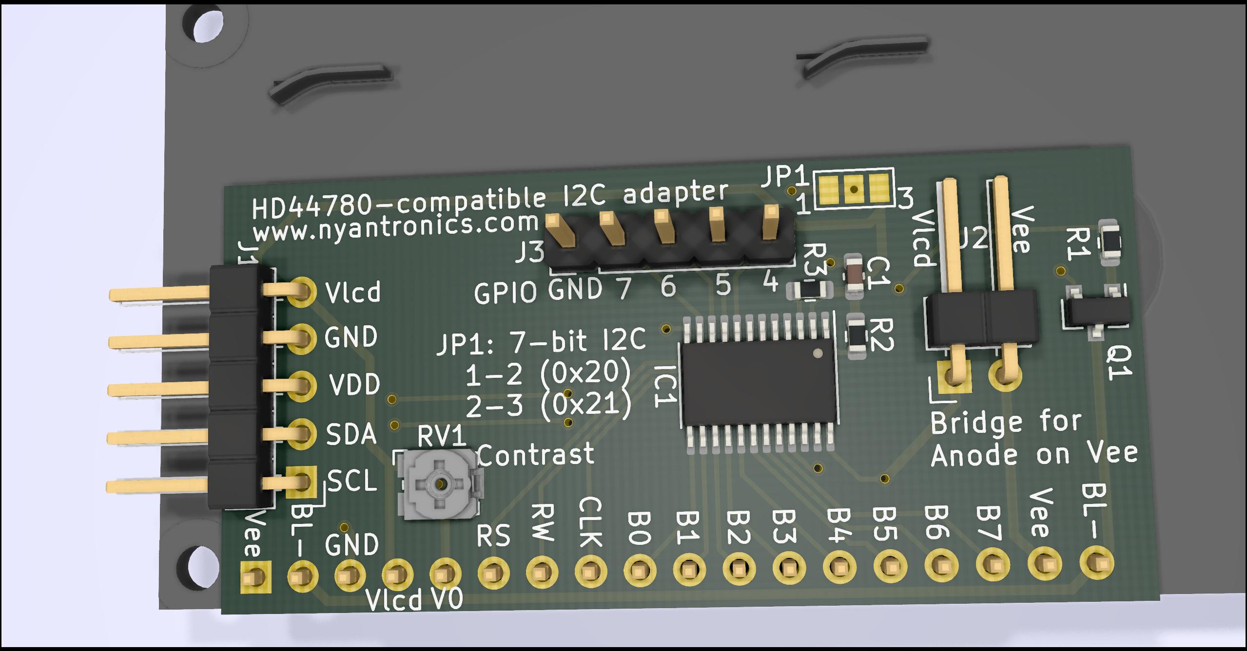
This project is an I2C expander module based around a Texas Instruments TCA6416A I2C GPIO expander. It allows for interfacing with a variety of 14 to 16-pin, HD44780-compatible displays:
This adapter is compatible with both 3.3V and 5V I2C bus levels. The 5-pin MCU/MPU side header has the following connections:
Default I2C 7-bit address is 0x20, set with JP1 (1-2 connected). To use the alternate 0x21 address, cut the connection on JP1 between pads 1 & 2, and connect 2-3.
Four GPIO pins from the I2C expander are broken out into a 5-pin header (J3). These can be freely used, limited by the TCA6416A's capabilities.
When a display is connected that does not use pin 16 for Vee (negative bias), but instead expects a 5V backlight supply voltage on this, connect the Vlcd-Vee connector with a jumper.
The backlight on/off state is controlled by GPIO 0 of the TCA6416A via Q1.
For contrast adjustment, a potentiometer on the board is provided.
This is currently a prototype design. It's likely that some things may not fully work as intended yet.
| Qty | Value | Footprint | References |
|---|---|---|---|
| 3 | 4k7 | Resistor_SMD:R_0603_1608Metric | R1, R2, R3 |
| 1 | 100nF | Capacitor_SMD:C_0603_1608Metric | C1 |
| 1 | Conn_01x02_Male | Connector_PinHeader_2.54mm:PinHeader_1x02_P2.54mm_Horizontal | J2 |
| 1 | Conn_01x05 | Connector_PinHeader_2.54mm:PinHeader_1x05_P2.54mm_Vertical | J3 |
| 1 | Conn_01x05_Male | Connector_PinHeader_2.54mm:PinHeader_1x05_P2.54mm_Horizontal | J1 |
| 1 | Conn_01x18_Male | Connector_PinHeader_2.54mm:PinHeader_1x18_P2.54mm_Vertical | J4 |
| 1 | Q_NPN_BCE | Package_TO_SOT_SMD:SOT-23 | Q1 |
| 1 | R_POT_Small | Potentiometer_SMD:Potentiometer_Bourns_TC33X_Vertical | RV1 |
| 1 | SolderJumper_3_Bridged12 | Jumper:SolderJumper-3_P1.3mm_Bridged12_Pad1.0x1.5mm_NumberLabels | JP1 |
| 1 | TCA6416APWR | Package_SO:TSSOP-24_4.4x7.8mm_P0.65mm | IC1 |
github-linguist/linguist
Language Savant. If your repository's language is being reported incorrectly, send us a pull request!


google/mozc-devices
Circuit diagrams and firmware source code for Gboard DIY keyboards


hackclub/OnBoard
💡 Join 1,000 teenagers and make your first PCB with a $100 grant!

VoronDesign/Voron-Tap
Tap is a nozzle-based z-probe for the V2 and Trident printer designs. The entire toolhead moves to trigger an optical switch. Tap offers many advantages:

stacksmashing/pico-tpmsniffer
A simple, very experimental TPM sniffer for LPC bus
It measures 23 × 48 mm and has 2 copper layers, 1.6 mm thick.
12 parts. The full list of its parts is on this page, with links to each part's symbol and footprint where PCBKit's library has them.
From the MayaPosch/HD44780_i2c repository on GitHub, at the commit this page was made from: the board is HD44780_i2c.kicad_pcb. PCBKit opens the board in the browser, with nothing to install.
Its repository publishes it under the BSD-3-Clause licence: you may reuse it on that licence's terms (keep the author's notice, and for a copyleft licence share your changes alike).