2 layers39.2 × 28 mm
Pin interposer
MaxMaeder/OpenPin
OpenPin: use your Humane Ai Pin again. Installable in a few clicks & without any ADB certs!
4 parts57
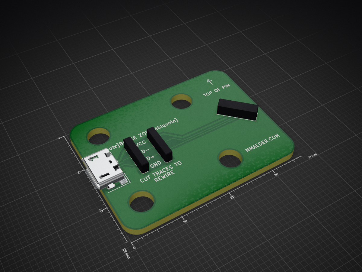
 MaxMaeder/OpenPin57
OpenPin: use your Humane Ai Pin again. Installable in a few clicks & without any ADB certs!
Pin interposer is an open-source printed circuit board by MaxMaeder, from the MaxMaeder/OpenPin repository on GitHub. It is a 2-layer board of 37 × 28 mm with 4 parts on 5 nets, routed with 22 tracks and 0 vias.
OpenPin is an open-source project which lets you use your Ai Pin after Humane bricked them. You can install it in a few clicks & without any ADB certs!
Please see OpenPin.org for installation and usage instructions.
| Qty | Name | Where to Buy |
|---|---|---|
| 4 | M2x8mm Hex Screws | Amazon |
| 4 | M2 Hex Locknuts | Amazon |
| 4 | Small Magnets | Amazon |
| 1 | Micro-USB Port | DigiKey |
| 1 | Pogo-Pin Assembly | DigiKey |
If you order the PCB with the USB-port already soldered (as in the instructions below) you do NOT need to buy the 'Micro-USB Port' part.
You will also need soldering tools and a 3D printer, depending on how much you choose to do yourself (versus using a service).
The following instructions are for if you want to buy the PCBs with the surface mount USB port already soldered.
These instructions are for JLCPCB. I don't have any affiliation, I just like them.
Upload gerbers
pin-interposer.zip, go to JLCPCB.com, and simply upload into the file dropboxSet PCB details
Upload assembly files
bom.csv into the left dropbox & positions.csv into the right, then click nextSet parts to assemble

10118193-0001LF, and search & select itClick through rest of process and check out!
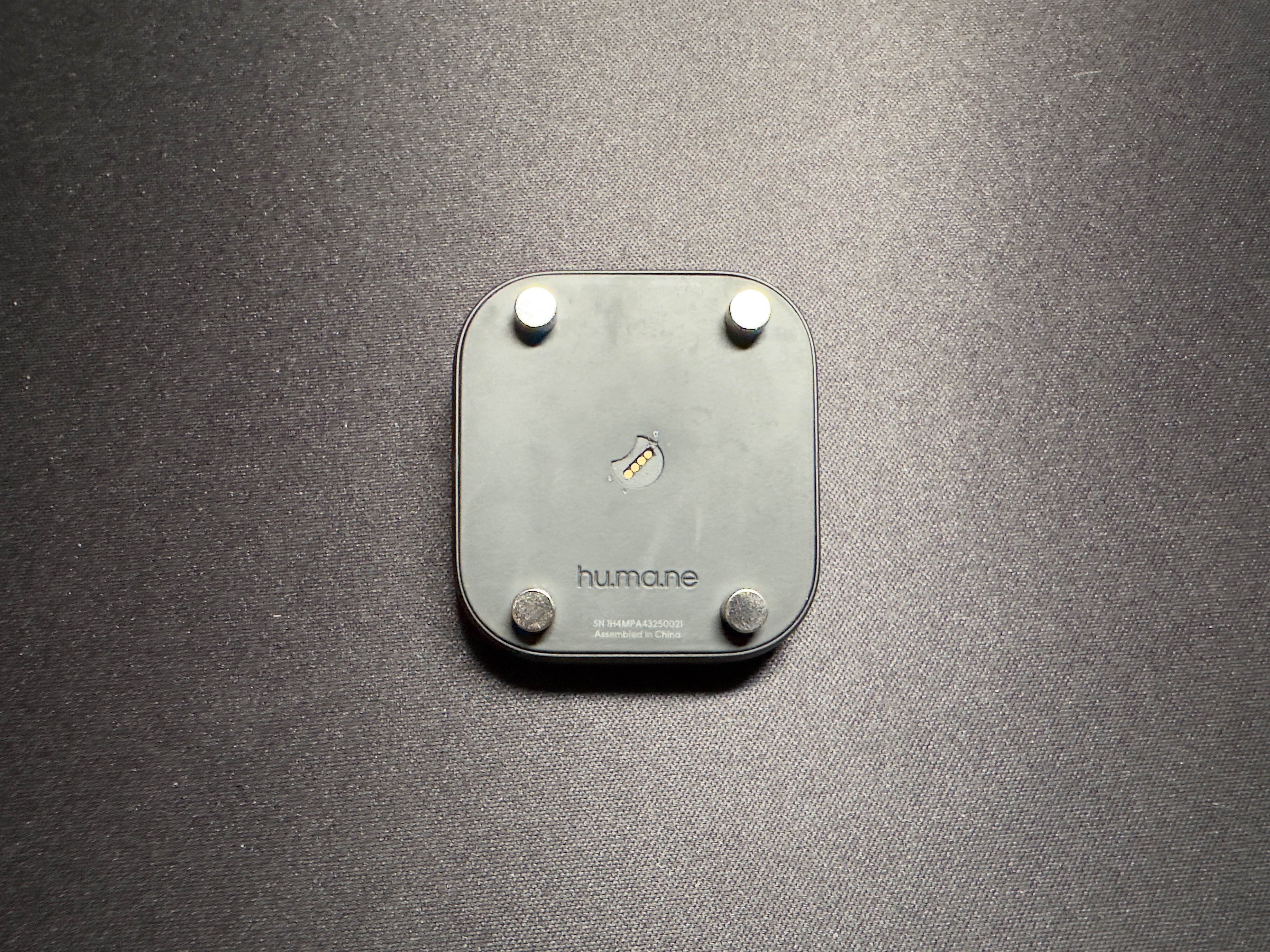
Putting the parts together
Screwing everything in
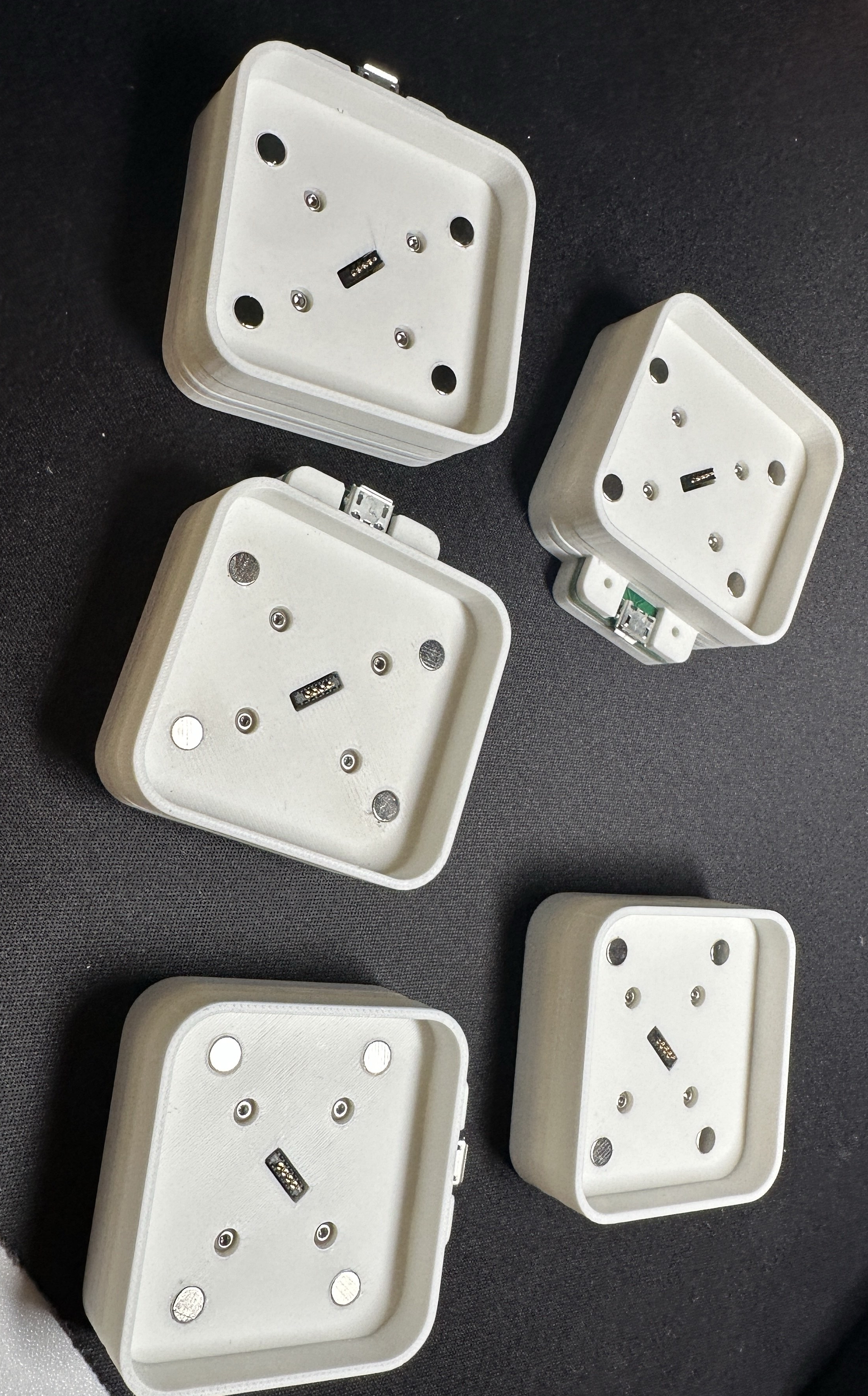
Install magnets
⚠️ It's really important you get the orientation of the magnets correct!
| Qty | Value | Footprint | References |
|---|---|---|---|
| 2 | Conn_01x04_Pin | debug-pads:4-smd-pads | J2, J3 |
| 1 | Conn_01x04_Pin | spring-conn:854-22-004-10-001101 | J4 |
| 1 | USB_B_Mini | Connector_USB:USB_Micro-B_Amphenol_10118193-0001LF_Horizontal | J1 |
MaxMaeder/OpenPin
OpenPin: use your Humane Ai Pin again. Installable in a few clicks & without any ADB certs!

joypad-ai/joypad-os
Universal controller firmware for building adapters, dongles, and custom controllers.


hackclub/OnBoard
💡 Join 1,000 teenagers and make your first PCB with a $100 grant!

tardate/LittleArduinoProjects
a collection of "Little Electronic & Arduino Projects", most involving electronics or an Arduino in one way or another!

drandyhaas/KiCadRoutingTools
A set of Python/Rust tools to aid routing in KiCad

osy/XG_Mobile_Station
Open source eGPU dock for ROG Ally and ROG Flow

Luos-io/luos_engine
Open-source and real-time orchestrator for cyber-physical-systems, to easily design, test and deploy embedded applications and digital twins.

NVNTLabs/switch2-SDEX2M2
Micro SD Express to M.2 NVME Adapter for Nintendo Switch 2
It measures 37 × 28 mm and has 2 copper layers, 1.6 mm thick.
4 parts. The full list of its parts is on this page, with links to each part's symbol and footprint where PCBKit's library has them.
From the MaxMaeder/OpenPin repository on GitHub, at the commit this page was made from: the board is interposer/pcb/v1/pin-interposer.kicad_pcb and its schematic interposer/pcb/v1/pin-interposer.kicad_sch. PCBKit opens the board in the browser, with nothing to install.
Its repository states no licence, so its author keeps all rights: ask MaxMaeder before reusing the design.