
2 layers60 × 55.1 mm
Controller
MattisLind/SPACEWAR
Classic SPACE WAR game for PDP-11 transcribed from original source
11 parts31

 MattisLind/SPACEWAR31
Classic SPACE WAR game for PDP-11 transcribed from original source
BreakoutBoard is an open-source printed circuit board by MattisLind, from the MattisLind/SPACEWAR repository on GitHub. It is a 2-layer board of 134 × 76.2 mm with 26 parts on 36 nets, routed with 289 tracks and 29 vias.
It is built around the 74HC14. Its parts include 7 connectors, 4 capacitors, 2 inductors, 1 resistor and 1 IC. It belongs with the microcontroller boards boards of this library.
Here is the needed information to build a basic joystick.
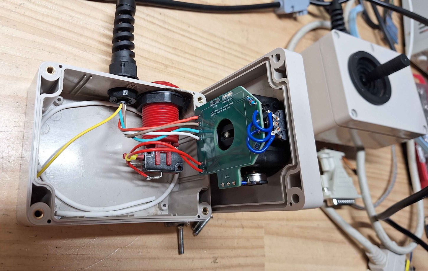
There are quite a few options to choose from, and sometimes the specifications are difficult to find. This set up has been tested with a joystick that uses potentiometers with the range of 0 to 5kOhm and a range of 50°.
Searching JH-D202X on Aliexpress should provide you with several options to pick from.
The case is a little tight, so spend some time to work out where you want to place things. Take care to allow space for the nut that holds the button. I have included some KiCad files I used to laser cut holes into the project box (see cut_template_files). You should be able to print them in paper and use them as a template or just for some dimensions. Mount the cable, strain relief and push button.
In my case I have use the following assignments:
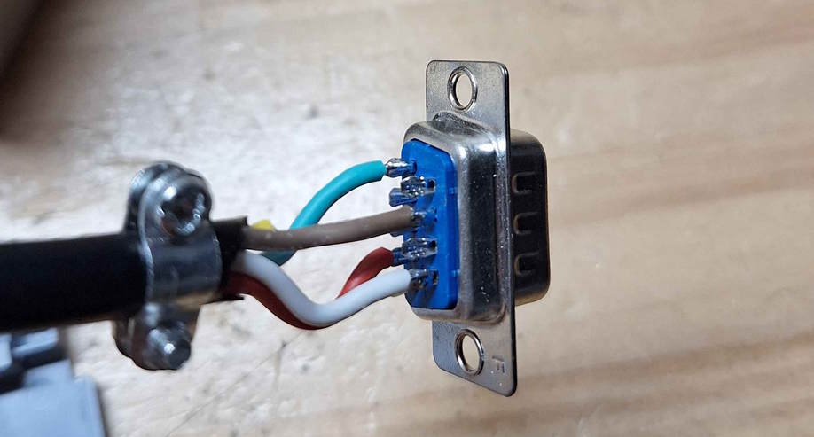
On the DB9 Connector I have used the following:
If you build the controller and find that Acceleration and Angle are swapped you CAN"T just swap the Acceleration and Angle wires. This is because the the fire button is connected to the Acceleration signal. Instead you must rotate the joystick.
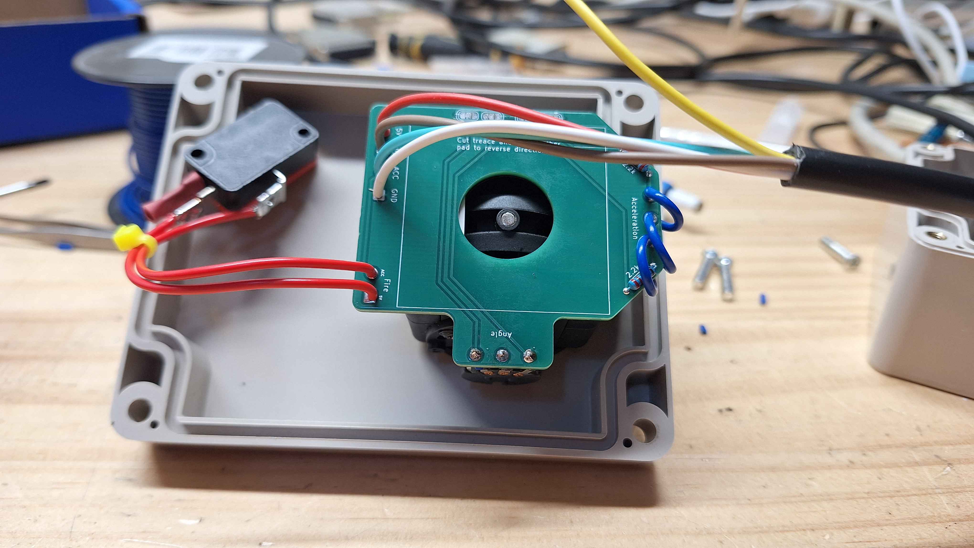
Take note of the orientation of the joystick relative to the case, otherwise you may find your controls are backwards!
Before you start make sure you joystick and button fit in the case. Also make sure you have feed cable through the project box before soldering it to the PCB.
| Qty | Value | Footprint | References |
|---|---|---|---|
| 4 | Jumper_NC_Small | Connector_PinHeader_2.54mm:PinHeader_1x02_P2.54mm_Vertical | JP1, JP2, JP3, JP4 |
| 4 | MountingHole | MountingHole:MountingHole_3.2mm_M3 | H2, H5, H6, H7 |
| 3 | Conn_Coaxial | Connector_Coaxial:BNC_TEConnectivity_1478204_Vertical | J5, J6, J7 |
| 3 | MountingHole | MountingHole:MountingHole_6.4mm_M6 | H1, H3, H4 |
| 2 | CP_Small | Capacitor_THT:CP_Radial_D5.0mm_P2.50mm | C2, C4 |
| 2 | C_Small | Capacitor_THT:C_Disc_D4.3mm_W1.9mm_P5.00mm | C1, C3 |
| 2 | DB9_Female_MountingHoles | Connector_Dsub:DSUB-9_Female_Vertical_P2.77x2.84mm_MountingHoles | J2, J3 |
| 2 | L | Inductor_THT:L_Radial_D7.2mm_P3.00mm_MuRATA_1700 | L1, L2 |
| 1 | 74HC14 | Package_DIP:DIP-14_W7.62mm | U1 |
| 1 | Conn_02x20_Odd_Even | Connector_PinHeader_2.54mm:PinHeader_2x20_P2.54mm_Horizontal | J1 |
| 1 | DB15_Female_MountingHoles | Connector_Dsub:DSUB-15_Female_Vertical_P2.77x2.84mm_MountingHoles | J4 |
| 1 | R_Small | Resistor_THT:R_Axial_DIN0207_L6.3mm_D2.5mm_P10.16mm_Horizontal | R1 |
MattisLind/SPACEWAR
Classic SPACE WAR game for PDP-11 transcribed from original source

BlueSCSI/BlueSCSI-v2
BlueSCSI v2/Ultra - an open source, open hardware, SCSI emulator using the Pi Pico PR2040 and Pico 2 RP2350

keirf/pcb-projects
The old Kickstart switcher documentation is here.

anyshake/explorer
🌏 Detecting seismic wave using 3 geophones and 3-axis accelerometer, pack & send data to AnyShake Observer over RS232 / RS485 serial.

nicolacimmino/PLC-14500
Retro trainer board based on the MC14500 1-bit ICU. The project is OSHW certified and a ready to assemble kit is available on Tindie.


transistorfet/computie
A collection of 68k computer projects, including a unix-like operating system written in C that runs on them

sbstnh/programmable_precision_resistor
A SCPI programmable precision resistor

It measures 134 × 76.2 mm and has 2 copper layers, 1.6 mm thick.
26 parts, built around the 74HC14. The full list of its parts is on this page, with links to each part's symbol and footprint where PCBKit's library has them.
From the MattisLind/SPACEWAR repository on GitHub, at the commit this page was made from: the board is breakoutBoard/breakoutBoard.kicad_pcb and its schematic joystick/controller.kicad_sch. PCBKit opens the board in the browser, with nothing to install.
Its repository states no licence, so its author keeps all rights: ask MattisLind before reusing the design.