4 layers45.8 × 30.4 mm
Battle bot pcb
MarkusVLA/robot-controller
150g combat robot controller PCB and firmware
66 parts3Apache-2.0

 MarkusVLA/Plant-Health-Meter2
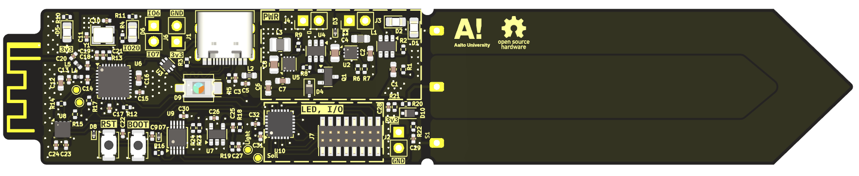
Plant Health Meter is an open-source printed circuit board by MarkusVLA, from the MarkusVLA/Plant-Health-Meter repository on GitHub, published under the MIT licence. It is a 4-layer board of 136.2 × 25 mm with 101 parts on 74 nets, routed with 785 tracks and 258 vias.
It is built around the ESP32-C3FH4X, ADS1115IDGS and BME280, with the OPA340NA, TPS62172DSG and TCA9555RTWR(UMW) among its other parts. Its parts include 32 capacitors, 24 resistors, 10 ICs, 10 diodes and 7 connectors. It belongs with the ESP32 and RISC-V boards of this library.


This repository contains Aalto AAN-C2009 project device hardware configuration and embedded software for a plant health monitoring system based on the ESP32c3 SoC.
PCB design done in KiCad.
 Schematic: PDF
Embedded software is written in C using the ESP-IDF (Espressif IoT Development Framework) ESP programming guide
See the schematic for detailed I/O connections and sensor bus configuration.
main/ folder create private_config.h file, with following definitions:
#define FIREBASE_HOST "xxx.firebasedatabase.app" - url of the firebase realtime database#define FIREBASE_AUTH "" - authentication token for the firebase - (TODO: not tested yet with protected database)idf.py set-target esp32c3idf.py menuconfig:
partitions.csv.idf.py build flash monitorBy default, there are no Wi-Fi credentials set. The device will immediately enter Bluetooth setup mode on boot.
For setup, you’ll need a mobile app capable of sending data over BLE, such as nRF Connect.
When the device is in Bluetooth setup mode, one of its LEDs will begin blinking. You can then find the device in the app under the name:
PLANT_SENSOR_01
Press Connect to establish a Bluetooth connection.
Once connected, look for Advertised Services in the device details. Find the characteristic that supports both Read and Write, and tap the up arrow (⬆️) to write data.
Select UTF-8 as the encoding format and send a message with the following structure:
device_id:wifi_ssid:wifi_passwordFor example:
sensor1:mywifi:secret_passwordAfter sending the credentials, the device will restart and attempt to connect to the specified Wi-Fi network.
Once connected, sensor data will be sent to Firebase under the provided device_id.
Important Notes:
device_id can contain only letters, digits, and underscores (e.g., plant_sensor_1).3.7V Li-ion battery or USB power
| Qty | Value | Footprint | References |
|---|---|---|---|
| 18 | 100n | Capacitor_SMD:C_0402_1005Metric | C3, C13, C14, C15, C17, C19, C21, C22, C23, C24, C26, C27, C29, C30, C31, C32 +2 |
| 8 | 5.1k | Resistor_SMD:R_0402_1005Metric | R2, R3, R5, R12, R14, R15, R16, R17 |
| 6 | 10u | Capacitor_SMD:C_0603_1608Metric | C1, C2, C6, C7, C12, C16 |
| 5 | Conn_01x02 | Connector_PinHeader_2.54mm:PinHeader_1x02_P2.54mm_Vertical | J1, J2, J3, J4, J6 |
| 4 | 100k | Resistor_SMD:R_0402_1005Metric | R7, R9, R23, R24 |
| 4 | LED | LED_SMD:LED_0805_2012Metric_Pad1.15x1.40mm_HandSolder | D1, D2, D5, D6 |
| 4 | TestPoint | TestPoint:TestPoint_Pad_D1.0mm | TP1, TP2, TP3, TP4 |
| 3 | 1k | Resistor_SMD:R_0402_1005Metric | R1, R10, R11 |
| 3 | ESD9B5.0ST5G | Diode_SMD:D_SOD-923 | D3, D7, D8 |
| 2 | 10k | Resistor_SMD:R_0402_1005Metric | R4, R20 |
| 2 | 15p | Capacitor_SMD:C_0402_1005Metric | C10, C11 |
| 2 | 2.2p | Capacitor_SMD:C_0402_1005Metric | C18, C20 |
| 2 | 22u | Capacitor_SMD:C_0805_2012Metric | C4, C8 |
| 2 | 510 | Resistor_SMD:R_0402_1005Metric | R19, R22 |
| 2 | LOGO | LOGO | G***, G*** |
| 1 | 10 | Resistor_SMD:R_0402_1005Metric | R13 |
| 1 | 1M | Resistor_SMD:R_0402_1005Metric | R21 |
| 1 | 1n | Capacitor_SMD:C_0402_1005Metric | C28 |
| 1 | 1u | Inductor_SMD:L_0805_2012Metric | L1 |
| 1 | 2.2n | Inductor_SMD:L_0402_1005Metric | L4 |
| 1 | 2.2n | Inductor_SMD:L_0603_1608Metric | L2 |
| 1 | 2.2u | Inductor_SMD:L_1008_2520Metric | L3 |
| 1 | 2.6n | Inductor_SMD:L_0402_1005Metric | L5 |
| 1 | 220n | Capacitor_SMD:C_0402_1005Metric | C25 |
| 1 | 33k | Resistor_SMD:R_0402_1005Metric | R18 |
| 1 | 40MHz | Crystal:Crystal_SMD_3225-4Pin_3.2x2.5mm | Y1 |
| 1 | 470k | Resistor_SMD:R_0402_1005Metric | R8 |
| 1 | 570k | Resistor_SMD:R_0402_1005Metric | R6 |
| 1 | ADS1115IDGS | Package_SO:TSSOP-10_3x3mm_P0.5mm | U9 |
| 1 | AO3401A | Package_TO_SOT_SMD:SOT-23 | Q1 |
| 1 | Antenna_Shield | RF_Antenna:Texas_SWRA117D_2.4GHz_Left | AE1 |
| 1 | BAT54J | Diode_SMD:D_SOD-323F | D10 |
| 1 | BAT60A | Diode_SMD:D_SOD-323 | D4 |
| 1 | BME280 | Package_LGA:Bosch_LGA-8_2.5x2.5mm_P0.65mm_ClockwisePinNumbering | U8 |
| 1 | BPW34-SMD | OptoDevice:Osram_BPW34S-SMD | D9 |
| 1 | Boot | Button_Switch_SMD:SW_Push_SPST_NO_Alps_SKRK | SW1 |
| 1 | Conn_02x08_Counter_Clockwise | Connector_PinHeader_1.27mm:PinHeader_2x08_P1.27mm_Vertical_SMD | J7 |
| 1 | ESP32-C3FH4X | Package_DFN_QFN:QFN-32-1EP_5x5mm_P0.5mm_EP3.7x3.7mm | U6 |
| 1 | LOGO | silkscreen-pictures:aalto | G*** |
| 1 | LTC4412xS6 | Package_TO_SOT_SMD:TSOT-23-6 | U4 |
| 1 | OPA340NA | Package_TO_SOT_SMD:SOT-23-5 | U7 |
| 1 | Reset | Button_Switch_SMD:SW_Push_SPST_NO_Alps_SKRK | SW2 |
| 1 | TCA9555RTWR | Package_DFN_QFN:WQFN-24-1EP_4x4mm_P0.5mm_EP2.45x2.45mm | U10 |
| 1 | TP4057 | Package_TO_SOT_SMD:TSOT-23-6 | U1 |
| 1 | TPS61022 | Package_DFN_QFN:Texas_RWU0007A_VQFN-7_2x2mm_P0.5mm | U2 |
| 1 | TPS62172DSG | Package_SON:WSON-8-1EP_2x2mm_P0.5mm_EP0.9x1.6mm_ThermalVias | U5 |
| 1 | USBLC6-2P6 | Package_TO_SOT_SMD:SOT-666 | U3 |
| 1 | USB_C_Receptacle_USB2.0_14P | Connector_USB:USB_C_Receptacle_HRO_TYPE-C-31-M-12 | J5 |
| 1 | ~ | Project_Library:Moisture_sensor_pads | S1 |
MarkusVLA/robot-controller
150g combat robot controller PCB and firmware


makerspacelt/WormControl-Relay15x5t15-ControlBoard
Dev NOTE: before commit, run ./kibot.sh to regenerate documentation, bom, gerbers and other assets.


vagarthgaurav/ESP32-C3-breakout-board
A simple breakout board for the ESP32-C3 Microcontroller. It uses a chip antenna for wifi and bluetooth. It has an RGB LED on pin 10.

windmoondreamer/pairing-voice-cube
아이가 목소리를 녹음하고, 부모가 버튼을 눌러 재생하는 장치의 회로기판 프로젝트. 80mm 큐브 케이스 · 최대 45초 녹음 · 내장 플래시 · 배터리 구동.

akbar-q/Circuits-PCB-HardwareDesign
The High Voltage Arc Detector is a non-contact RF-based sensing system that detects high-voltage electrical arcs.

cheyao/nRF52840-microstamp
nRF52840 Stamp for easy low powered bluetooth applications
It measures 136.2 × 25 mm and has 4 copper layers, 1.6 mm thick.
101 parts, built around the ESP32-C3FH4X, ADS1115IDGS, BME280 and OPA340NA. The full list of its parts is on this page, with links to each part's symbol and footprint where PCBKit's library has them.
From the MarkusVLA/Plant-Health-Meter repository on GitHub, at the commit this page was made from: the board is PCB/Plant-health-meter.kicad_pcb and its schematic PCB/LEDS.kicad_sch. PCBKit opens the board in the browser, with nothing to install.
Its repository publishes it under the MIT licence: you may reuse it on that licence's terms (keep the author's notice, and for a copyleft licence share your changes alike).