2 layers78 × 60 mm
 MReavley/CyberSliceKeyboard30
42/36 key ergo split keyboard using a RP2040
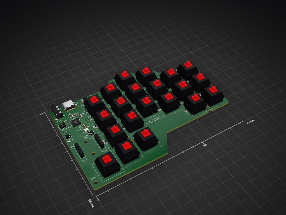
RP2040 Board V1.0 is an open-source printed circuit board by MReavley, from the MReavley/CyberSliceKeyboard repository on GitHub, published under the MIT licence. It is a 2-layer board of 144 × 98 mm with 92 parts on 81 nets, routed with 836 tracks and 64 vias.
It is built around the RP2040, W25Q128JVSIQ and AMS1117-3.3. Its parts include 23 switches, 22 diodes, 16 capacitors, 13 resistors and 5 connectors. It belongs with the keyboards and input boards and the RP2040 boards of this library.


42/36 key split keyboard using RP2040, with the same layout (in 36 key configuration) as my previous design, the Slice 36. The goal was primarily to experience designing a microcontroller directly on the PCB, but I also wanted to try to take advantage of the large number of GPIO pins on the RP2040. There are 8 additional GPIO (2 analog capable) on the PCB with the intention of adding functionality through magnetic pogo connectors, but that is still a work in progress.


This board is just a prototype, and there are a couple pointers to watch out for:
Reversible PCB: Since the PCB is reversible, solder on the trrs connector on opposite sides of the PCB for each half. The USB-C connector for the left half will be on the bottom side, which does necessitate taller rubber feet unfortunately.
Components on the rear:
These components will not be assembled by basic PCBa, but the parts can be scavenged from spare assembled PCBs (per side)
Additional components:
Reset and boot switches may need to be renamed in the BOM file (not using SW1 and SW2) for them to be auto-selected by PCBa service
Case:


| Qty | Value | Footprint | References |
|---|---|---|---|
| 21 | Cherry_Doublesided | MxSwitches:SW_MX_reversible | Sw1, Sw2, Sw3, Sw4, Sw10, Sw11, Sw12, Sw13, Sw14, Sw15, Sw16, Sw17, Sw18, Sw19, Sw20, Sw21 +5 |
| 21 | D | Diode_SMD:D_SOD-323_HandSoldering | D2, D3, D4, D10, D11, D12, D13, D14, D15, D16, D17, D18, D19, D20, D21, D22 +5 |
| 9 | 100n | Capacitor_SMD:C_0603_1608Metric_Pad1.08x0.95mm_HandSolder | C7, C8, C9, C10, C11, C12, C13, C14, C15 |
| 8 | , , , , , , , | ||
| 3 | 1k | Resistor_SMD:R_0603_1608Metric | R3, R4, R6 |
| 3 | 5.1k | Resistor_SMD:R_0603_1608Metric | R1, R2, R11 |
| 2 | 1u | Capacitor_SMD:C_0603_1608Metric_Pad1.08x0.95mm_HandSolder | C6, C16 |
| 2 | 22u | Capacitor_SMD:C_0603_1608Metric | C1, C2 |
| 2 | 27 | Resistor_SMD:R_0603_1608Metric_Pad0.98x0.95mm_HandSolder | R7, R8 |
| 2 | 27p | Capacitor_SMD:C_0603_1608Metric | C4, C5 |
| 2 | 5.1k | Resistor_SMD:R_0603_1608Metric_Pad0.98x0.95mm_HandSolder | R9, R10 |
| 2 | AudioJack4 | Connector_Audio:Jack_3.5mm_PJ320D_Horizontal | J2, J3 |
| 2 | Conn_01x05_MountingPin | Magnet:Magnet 5pin 2.54mm pitch through hole | J4, J5 |
| 2 | DNP | Resistor_SMD:R_0805_2012Metric_Pad1.20x1.40mm_HandSolder | R12, R13 |
| 2 | SW_SPST | Button_Switch_SMD:SW_SPST_PTS810 | SW1, SW2 |
| 1 | 100n | Capacitor_SMD:C_0603_1608Metric | C3 |
| 1 | 12MHz | Crystal:Crystal_SMD_3225-4Pin_3.2x2.5mm | Y1 |
| 1 | AMS1117-3.3 | Package_TO_SOT_SMD:SOT-223-3_TabPin2 | U1 |
| 1 | DNP | Resistor_SMD:R_0603_1608Metric | R5 |
| 1 | RED | LED_SMD:LED_0603_1608Metric | D1 |
| 1 | RP2040 | RP2040:RP2040 | U3 |
| 1 | USB_C_Receptacle_USB2.0 | Connector_USB:USB_C_Receptacle_HRO_TYPE-C-31-M-12 | J1 |
| 1 | W25Q128JVS | Package_SO:SOIC-8_5.23x5.23mm_P1.27mm | U2 |
The 91 most common of 92 parts.

OpenJBOD/rp2040
This repository contains the hardware design files OpenJBOD RP2040 Baseboard.

jpconstantineau/PyKey60
The PyKey60 is a custom programmable mechanical keyboard with a standard ANSI 60% keyboard layout compatible with any cases made for the GH60. The PyKey60 uses mechanical switches (Cherry MX type).

victorhook/asac-fc
asac fc is an rp2040 based flight controller made for FPV drone flying


autonomous-ai/autonomous-circuit
Chat with AI, get a verified PCB and a fab packet you can order.

souptik-samanta/Hackducky
Our board is powered by the reliable Raspberry Pi RP2040 microcontroller and includes 16 MB of flash storage, giving plenty of room for scripts and firmware.
It measures 144 × 98 mm and has 2 copper layers, 1.6 mm thick.
92 parts, built around the RP2040, W25Q128JVSIQ and AMS1117-3.3. The full list of its parts is on this page, with links to each part's symbol and footprint where PCBKit's library has them.
From the MReavley/CyberSliceKeyboard repository on GitHub, at the commit this page was made from: the board is Kicad/RP2040 Board V1.0.kicad_pcb and its schematic Kicad/RP2040 Board V1.0.kicad_sch. PCBKit opens the board in the browser, with nothing to install.
Its repository publishes it under the MIT licence: you may reuse it on that licence's terms (keep the author's notice, and for a copyleft licence share your changes alike).