2 layers265.5 × 132.3 mm
Dashdash
Churrosoft/Dashdash
tablero de instrumentos por can para integrar con OpenEFI, cuando se nos ocurra algo mas original cambiamos el nombre
272 parts1MIT
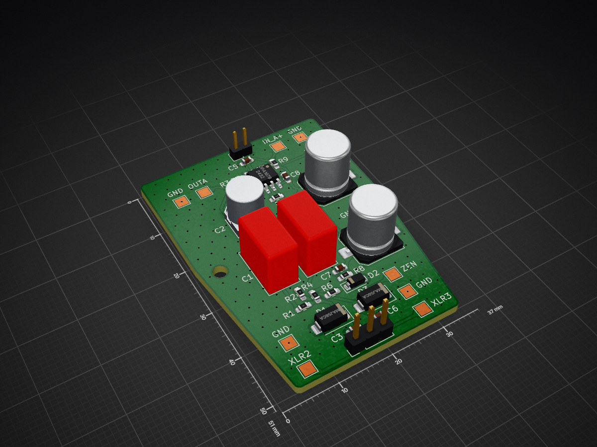
 MHeis22/P48ElectretMicPCB
Phantom powered OPA Alice / https://www.ti.com/lit/an/sboa320a/sboa320a.pdf?ts=1773332275188 resembling Electret mic Impedance Converter with balanced out.
ElectretXLRMic is an open-source printed circuit board by MHeis22, from the MHeis22/P48ElectretMicPCB repository on GitHub. It is a 2-layer board of 37 × 51 mm with 38 parts on 12 nets, routed with 75 tracks and 235 vias.
It is built around the OPA1678ID and SMAJ58CA. Its parts include 10 capacitors, 9 resistors, 3 diodes, 2 connectors and 1 IC.


Ordered the PCBs from JLCPCB and components from Mouser. Initial test on 26.3.26 provided great results. Noticeably less bass heavy than the Fifine K688 which was used with XLR. Both microphones tested on a Scarlett 2i2 4th generation.
Autogenerated by GitHub Command Center
| Metric | Value |
|---|---|
| Board Dimensions | 37.0 x 51.01 mm |
| Total Area | 1887.24 mm² |
| Layer Count | 2 Copper Layers |
| Total Components | 27 |
| SMD Components | 21 |
| THT Components | 4 |
| Unique Parts | 25 |
| KiCad Version | 10.0.1 |
| Metric | Value |
|---|---|
| Vias | 235 Total (235 TH, 0 Blind, 0 Micro) |
GND| Reference | Component | Function / Description |
|---|---|---|
| U1 | OPA1678 | Low-Distortion Audio Operational Amplifiers, SOIC-8/VSSOP-8 |
| Reference | Type | Component | Description |
|---|---|---|---|
| J2 | Connector | MIC | Generic connector, single row, 01x02, script generated |
| J1 | Connector | XLR3 | Header for XLR pins |
| J3 | Connector | XLR3 | XLR Connector, Female, 3 Pins |
| Component | Breakdown |
|---|---|
| Capacitor | 5x0603 and 5xOther |
| Diode | 3xOther |
| Resistor | 9x0603 |
| Qty | Value | Footprint | References |
|---|---|---|---|
| 4 | GND1 | TestPoint:TestPoint_Pad_2.0x2.0mm | TP1, TP2, TP8, TP10 |
| 3 | 100pF | Capacitor_SMD:C_0603_1608Metric_Pad1.08x0.95mm_HandSolder | C3, C5, C6 |
| 2 | 100 | Resistor_SMD:R_0603_1608Metric_Pad0.98x0.95mm_HandSolder | R1, R2 |
| 2 | 1k | Resistor_SMD:R_0603_1608Metric_Pad0.98x0.95mm_HandSolder | R5, R7 |
| 2 | 1uF | Capacitor_SMD:C_0603_1608Metric_Pad1.08x0.95mm_HandSolder | C7, C8 |
| 2 | 2.2k | Resistor_SMD:R_0603_1608Metric_Pad0.98x0.95mm_HandSolder | R4, R6 |
| 2 | 3.3uF | Capacitor_THT:C_Rect_L10.3mm_W5.7mm_P7.50mm_MKS4 | C1, C4 |
| 2 | 33uF | Capacitor_SMD:C_Elec_8x10.2 | C9, C10 |
| 2 | SMAJ58CA | Diode_SMD:D_SMA | D1, D3 |
| 1 | 100k | Resistor_SMD:R_0603_1608Metric_Pad0.98x0.95mm_HandSolder | R3 |
| 1 | 10uF | SamacSys_Parts:CAPAE660X850N | C2 |
| 1 | 330 | Resistor_SMD:R_0603_1608Metric_Pad0.98x0.95mm_HandSolder | R8 |
| 1 | 7.5k | Resistor_SMD:R_0603_1608Metric_Pad0.98x0.95mm_HandSolder | R9 |
| 1 | D_Zener 8.2V | Diode_SMD:D_SOD-123 | D2 |
| 1 | MIC | Connector_PinHeader_2.00mm:PinHeader_1x02_P2.00mm_Vertical | J2 |
| 1 | MountingHole | MountingHole:MountingHole_2.5mm | H1 |
| 1 | MountingHole_GND | MountingHole:MountingHole_2.7mm_M2.5_DIN965_Pad_TopBottom | H2 |
| 1 | OPA1678 | Package_SO:SOIC-8_3.9x4.9mm_P1.27mm | U1 |
| 1 | U1A+ | TestPoint:TestPoint_Pad_2.0x2.0mm | TP6 |
| 1 | U1AOUT | TestPoint:TestPoint_Pad_2.0x2.0mm | TP4 |
| 1 | U1BOUT | TestPoint:TestPoint_Pad_2.0x2.0mm | TP5 |
| 1 | VCC | TestPoint:TestPoint_Pad_2.0x2.0mm | TP11 |
| 1 | XLR2 | TestPoint:TestPoint_Pad_2.0x2.0mm | TP3 |
| 1 | XLR3 | TestPoint:TestPoint_Pad_2.0x2.0mm | TP9 |
| 1 | XLR3 | Connector_PinHeader_2.54mm:PinHeader_1x03_P2.54mm_Vertical | J1 |
| 1 | Zener | TestPoint:TestPoint_Pad_2.0x2.0mm | TP7 |
Churrosoft/Dashdash
tablero de instrumentos por can para integrar con OpenEFI, cuando se nos ocurra algo mas original cambiamos el nombre


Churrosoft/kibot_test
export KICAD63DMODELDIR="/usr/share/kicad/3dmodels/" export KICAD6FOOTPRINTDIR="/usr/share/kicad/footprints/" export KICAD6SYMBOLDIR="/usr/share/kicad/symbols/" export KICAD6TEMPLATEDIR="/usr/share/kicad/template/"

UbiTrich/home-assistant-poe-satellite
ESP32-S3 PoE voice satellite for Home Assistant

Churrosoft/OpenEFI-PCB
Coleccion de PCB y planos recomendados para montar una OpenEFI


ishkabbible/Triple_Attenuverter_Mixer_v2
The TAM is three precision attenuators/attenuverters feeding into a 3-input, non-inverting mixer. The attenuXer sections are fully independent, and the output jacks are normalled to the mixer.

It measures 37 × 51 mm and has 2 copper layers, 1.6 mm thick.
38 parts, built around the OPA1678ID and SMAJ58CA. The full list of its parts is on this page, with links to each part's symbol and footprint where PCBKit's library has them.
From the MHeis22/P48ElectretMicPCB repository on GitHub, at the commit this page was made from: the board is ElectretXLRMic.kicad_pcb and its schematic ElectretXLRMic.kicad_sch. PCBKit opens the board in the browser, with nothing to install.
Its repository states no licence, so its author keeps all rights: ask MHeis22 before reusing the design.