

4 layers47.5 × 37 mm

 MAWoodMain/PowerMonitorMK35
Third version high resolution high speed AC power monitor
PowerMonitorMK3 is an open-source printed circuit board by MAWoodMain, from the MAWoodMain/PowerMonitorMK3 repository on GitHub. It is a 2-layer board of 125 × 41 mm with 93 parts on 84 nets, routed with 709 tracks and 250 vias.
It is built around the ESP32-WROVER and ADUM4152BRIZ. Its parts include 40 capacitors, 15 resistors, 8 connectors, 6 ICs and 4 diodes. It belongs with the ESP32 boards of this library.
The plan is to evaluate the ADE9153 IC using an initial PCB build with mains isolation for easy development and no real planned form factor.
Then assuming the IC checks out the schematic and PCB will be reissued without isolation and with a much tigher form factor to fit in a DIN rail enclosure so it can be wired into my home.
An extra prototype run may be required inbetween to evaluate isolation removal or to fix mistakes that render ISS1 unusable.
The ISS1 PCB is powered from the safe side using a micro USB cable and this power is isolated and used on the hot side, this circuit is based on the ADE9153's evaluation board schematic.
It is noteworthy that the hot side's GND is mains live and does present a serious safety risk.
I accept no liability for anyone else's use of this design.
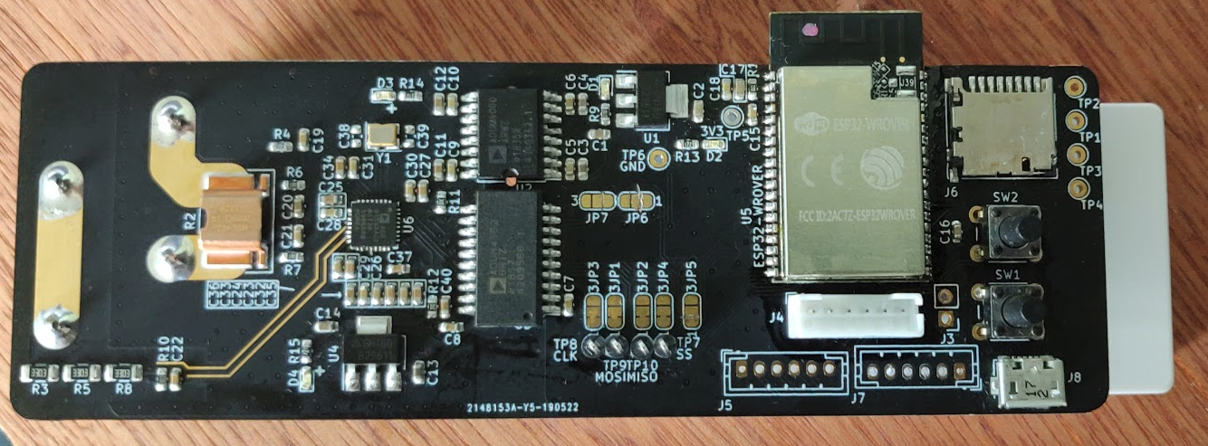
MOD A
MOD B
Currently in hardware testing phase, temporary non VCS projects are being used to evaluate the PCB, once this process is complete a formal firmware project will be added to VCS and developed
| Qty | Value | Footprint | References |
|---|---|---|---|
| 19 | 100nF | Capacitor_SMD:C_0603_1608Metric | C5, C6, C10, C15, C16, C18, C19, C20, C21, C24, C28, C29, C30, C31, C32, C33 +3 |
| 7 | 4.7uF | Capacitor_SMD:C_0603_1608Metric | C23, C25, C26, C27, C34, C35, C36 |
| 6 | 10uF | Capacitor_SMD:C_0603_1608Metric | C1, C3, C4, C11, C12, C13 |
| 4 | LED | LED_SMD:LED_0603_1608Metric | D1, D2, D3, D4 |
| 4 | MOSI_SEL | Jumper:SolderJumper-3_P1.3mm_Bridged12_RoundedPad1.0x1.5mm_NumberLabels | JP1, JP5, JP6, JP7 |
| 3 | 1K | Resistor_SMD:R_0603_1608Metric | R9, R10, R14 |
| 3 | 22uF | Capacitor_SMD:C_0603_1608Metric | C2, C14, C17 |
| 3 | 330K | Resistor_SMD:R_1206_3216Metric | R3, R5, R8 |
| 2 | 10K | Resistor_SMD:R_0603_1608Metric | R11, R12 |
| 2 | 150K | Resistor_SMD:R_0603_1608Metric | R6, R7 |
| 2 | 220 | Resistor_SMD:R_0603_1608Metric | R13, R15 |
| 2 | 30pF | Capacitor_SMD:C_0603_1608Metric | C38, C39 |
| 2 | AZ1117-3.3 | Package_TO_SOT_SMD:SOT-223-3_TabPin2 | U1, U4 |
| 2 | ESP_JTAG | Connector_JST:JST_PH_B6B-PH-K_1x06_P2.00mm_Vertical | J4, J5 |
| 1 | 0 | Resistor_SMD:R_0603_1608Metric | R4 |
| 1 | 100K | Resistor_SMD:R_0603_1608Metric | R1 |
| 1 | 12.288MHz 18pF | Crystal:Crystal_SMD_3225-4Pin_3.2x2.5mm | Y1 |
| 1 | 15nF | Capacitor_SMD:C_0603_1608Metric | C22 |
| 1 | 1uF | Capacitor_SMD:C_0603_1608Metric | C40 |
| 1 | 300u | Project:WSL4026 | R2 |
| 1 | 3V3 | Connector_Pin:Pin_D1.0mm_L10.0mm | TP5 |
| 1 | 470nF | Capacitor_SMD:C_0603_1608Metric | C37 |
| 1 | ADE9153A | Package_DFN_QFN:QFN-32-1EP_5x5mm_P0.5mm_EP3.1x3.1mm | U6 |
| 1 | ADuM4152BRIZ | Package_SO:SOIC-20W_7.5x12.8mm_P1.27mm | U3 |
| 1 | ADuM6000 | Package_SO:SOIC-16W_7.5x10.3mm_P1.27mm | U2 |
| 1 | BOOT_SW | Button_Switch_THT:SW_PUSH_6mm | SW1 |
| 1 | ESP32-WROVER | ESP32-WROVER-B__16MB_:XCVR_ESP32-WROVER-B_(16MB) | U5 |
| 1 | ESP32_BOOT | Connector_PinHeader_2.54mm:PinHeader_1x02_P2.54mm_Vertical | J3 |
| 1 | ESP_EINK | Connector_JST:JST_PH_B6B-PH-K_1x06_P2.00mm_Vertical | J7 |
| 1 | GND | Connector_Pin:Pin_D1.0mm_L10.0mm | TP6 |
| 1 | MAINS_IN | 1792229:PHOENIX_1792229 | J2 |
| 1 | MAINS_OUT | 1792229:PHOENIX_1792229 | J1 |
| 1 | MISO_SEL | Jumper:SolderJumper-3_P1.3mm_Bridged12_RoundedPad1.0x1.5mm_NumberLabels | JP2 |
| 1 | Micro_SD_Card | Connector_Card:microSD_HC_Hirose_DM3D-SF | J6 |
| 1 | RST_SW | Button_Switch_THT:SW_PUSH_6mm | SW2 |
| 1 | SCLK_SEL | Jumper:SolderJumper-3_P1.3mm_Bridged12_RoundedPad1.0x1.5mm_NumberLabels | JP3 |
| 1 | SS_SEL | Jumper:SolderJumper-3_P1.3mm_Bridged12_RoundedPad1.0x1.5mm_NumberLabels | JP4 |
| 1 | USB_B_Micro | Connector_USB:USB_Micro-B_Molex_47346-0001 | J8 |
| 1 | hMISO | Connector_Pin:Pin_D1.0mm_L10.0mm | TP4 |
| 1 | hMOSI | Connector_Pin:Pin_D1.0mm_L10.0mm | TP3 |
| 1 | hSCLK | Connector_Pin:Pin_D1.0mm_L10.0mm | TP2 |
| 1 | hSS | Connector_Pin:Pin_D1.0mm_L10.0mm | TP1 |
| 1 | vMISO | Connector_Pin:Pin_D1.0mm_L10.0mm | TP10 |
| 1 | vMOSI | Connector_Pin:Pin_D1.0mm_L10.0mm | TP9 |
| 1 | vSCLK | Connector_Pin:Pin_D1.0mm_L10.0mm | TP8 |
| 1 | vSS | Connector_Pin:Pin_D1.0mm_L10.0mm | TP7 |

ctag-fh-kiel/ctag-tbd
CTAG TBD >>to be determined<< an extendible open source Eurorack sound module


ctag-fh-kiel/esp32-eurorack-audio
Open source eurorack audio module based on ESP32

lucysrausch/sony-scopeman
Hardware Design files of a replacement mainboard for the Sony Watchman FD-10. This turns it into a bluetooth and WiFi-enabled vector display.

kbx81/ClimateSprinklerController
ESP32-based climate and sprinkler controller for use with ESPHome

SolderedElectronics/Soldered-Inkplate-10-hardware-design
Hardware design, BOM, gerbers and 3D files for Soldered-Inkplate-10 designed by Soldered Electronics.

har-in-air/ESP32_WROVER_BREAKOUT
Breadboard compatible breakout PCB for ESP32-WROVER with TPS82140 power supply
It measures 125 × 41 mm and has 2 copper layers, 1.6 mm thick.
93 parts, built around the ESP32-WROVER and ADUM4152BRIZ. The full list of its parts is on this page, with links to each part's symbol and footprint where PCBKit's library has them.
From the MAWoodMain/PowerMonitorMK3 repository on GitHub, at the commit this page was made from: the board is PCB/Power Monitor MK3.kicad_pcb. PCBKit opens the board in the browser, with nothing to install.
Its repository states no licence, so its author keeps all rights: ask MAWoodMain before reusing the design.