2 layers20 × 20 mm
Voltage datalogger afe
LukeVassallo/RL_PCB
RL_PCB is a novel learning-based method for optimising the placement of circuit components on a Printed Circuit Board (PCB).
9 parts76MIT

 LukeVassallo/RL_PCB76
RL_PCB is a novel learning-based method for optimising the placement of circuit components on a Printed Circuit Board (PCB).
Voltage datalogger adc0 is an open-source printed circuit board by LukeVassallo, from the LukeVassallo/RL_PCB repository on GitHub, published under the MIT licence. It is a 2-layer board of 20 × 20 mm with 9 parts on 18 nets.
Its parts include 4 capacitors, 4 resistors and 1 IC. It belongs with the sensors and measurement boards of this library.
[toc]
RL_PCB is an end-to-end Reinforcement Learning PCB placement methodology. The solution is inspired from cellular automata. The state of the circuit placement problem is distributed across all the components on the layout region. Every component can update it's positioning independently based on local and global information. The question of how to update the state, factoring in experience (i.e. past knowledge) is a particularly difficult one. We use reinforcement learning to learn ways of updating the state. We do so in a way that localised updates are not destructive to the global solution. Consequently the solution naturally comes out as an emergent property of the system.
You can learn more about this work by reading our DATE 24 paper. My Master thesis investigated "A graph placement methodology for fast chip design" proposed by Mirhoseini et al., and based on it's shortcomings proposed this solution.
If you find this work useful please cite us!
@inproceedings{Vassallo2024,
  author={Vassallo, Luke and Bajada, Josef},
  booktitle={2024 Design, Automation & Test in Europe Conference & Exhibition (DATE)},
  title={Learning Circuit Placement Techniques Through Reinforcement Learning with Adaptive Rewards},
  year={2024},
  volume={},
  number={},
  pages={1-6},
}
RL_PCB is a novel learning-based method for optimising the placement of circuit components on a Printed Circuit Board (PCB). Reinforcement learning is used to learn general policies for iteratively improving a circuit placement, leading to intuitive layouts while outperforming stochastic methods in terms of post-routing wirelength.
The main contribution of this work is:
 (a) (EW=0, HPWL=5, Overlap=5) |  (b) (EW=8, HPWL=0, Overlap=2) |  (c) (EW=0, HPWL=8, Overlap=2) |
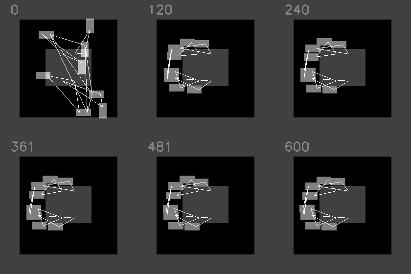 (d) (EW=0, HPWL=8, Overlap=2) | 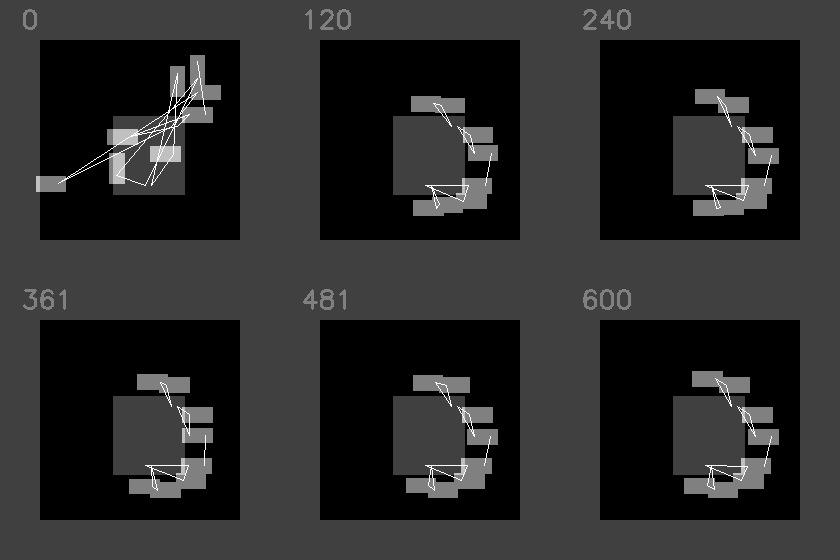 (e) (EW=8, HPWL=0, Overlap=2) | 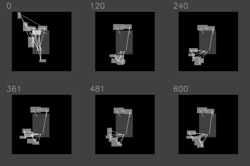 (f) (EW=8, HPWL=0, Overlap=2) |
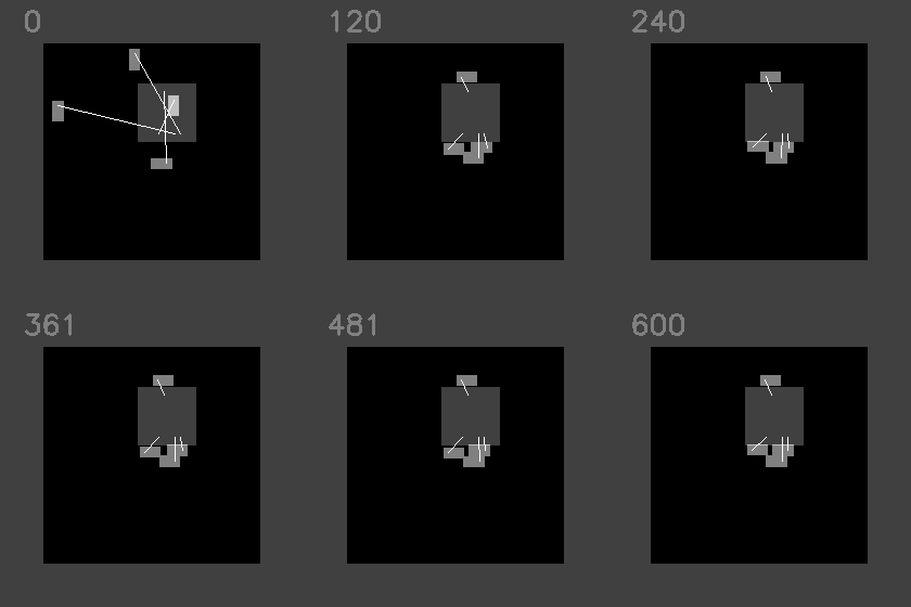 (g) (EW=8, HPWL=0, Overlap=2) | 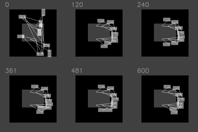 (h) (EW=2, HPWL=2, Overlap=6) | 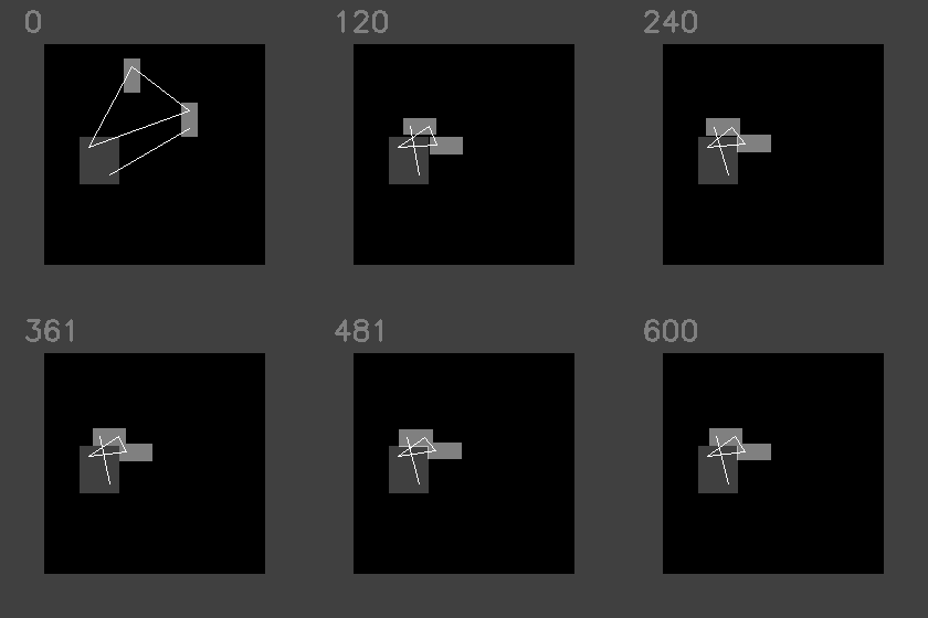 (i) (EW=2, HPWL=2, Overlap=6) |
Figure 1: Succesful policies optimising circuits not seen during training.
It is very important that the installation procedure is carried out while being in the root of the repository (i.e. the same location as the script install_tools_and_virtual_environment.sh)
The following packages must be installed on the system to compile libraries for parsing KiCAD PCB files (.kicad_pcb) and place-and-route tools.
sudo apt install python3-virtualenv build-essential libboost-dev libboost-filesystem-devTo ensure consistency, Python code requires the use of version 3.8. Moreover, virtual environments for Python are necessary to install dependencies within a limited scope, preventing any modifications to the system's configuration. If Python3.8 is not available by default through the package manager of your system, you can use the following code to add an apt repository that maintains previous versions and source the required version accordingly.
sudo add-apt-repository ppa:deadsnakes/ppa -y
sudo apt update
sudo apt install python3.8 python3.8-venvThe automated installation procedure makes the following changes to the local repository:
./install_tools_and_virtual_environment.sh --env_onlyIf you do not have CUDA 11.7 installed, you can install the CPU only. Tests an experiments will run significantly slower but works out of the box.
./install_tools_and_virtual_environment.sh --env_only --cpu_onlyIf you require a different version of CUDA, please make the following changes and run install_tools_and_virtual_environment.sh without any options:
setup.sh script, change the CUDA path to point to your installation of CUDA.install_tools_and_virtual_environment.sh script, change the PyTorch libraries to use your CUDA version.Using a CPU device or alternative CUDA version will yield different results than the accompanying pdf reports for tests and experiments.
Always source the environment setup script before running any tests or experiments. The script should be run from the root of the repository
cd <path-to-rl_pcb>
source setup.sh
Run an experiment
cd experiments/00_parameter_exeperiments
./run.sh
Run a test - tests are used to validate the correct operation of the source code. They are periodically run in a Continuous Integration (CI) environment.
cd tests/01_training_td3_cpu
./run.sh
The script run.sh will perform the following:
run_config.txt that is located within the same directoryreport_config.py, located within the same directory.The generated files can be cleaned by running the following:
./clean.shEvery test and experiment contains a directory called expected results that contains pre-generated reports. Should you run the experiments as provided, identical results are to be expected.
This section provides an optional setup procedure to remove the Nvidia GPU driver and all dependent libraries and perform a fresh install. The commands in this section make big changes to your system. Please read carefully before running commands Some command changes will be required.
sudo apt-get --purge remove cuda* *cublas* *cufft* *curand* *cusolver* *cusparse* *npp* *nvjpeg* *nsight*sudo apt-get --purge remove *nvidia*sudo apt remove libcudnn* libcudnn*-devTo install the driver, you can start by issuing the command ubuntu-drivers devices and identifying the latest third-party non-free version. Once you have identified the appropriate version, use apt to install the driver. After installing the driver, reboot your system and issue the command nvidia-smi to identify the full driver version. In the upcoming section, you will need this information to determine which CUDA version is supported.
To ensure that your device driver is compatible with CUDA, you'll need to check the compatibility using the following link: https://docs.nvidia.com/deploy/cuda-compatibility/. Once you've confirmed the compatibility, you can proceed to the CUDA Toolkit Archive at https://developer.nvidia.com/cuda-toolkit-archive. From there, select version 11.7 and choose the appropriate platform parameters from the "Select Target Platform" section. Next, download the runfile (local) and proceed with the installation process. Finally, follow the installation instructions carefully and avoid installing the driver when prompted.
wget https://developer.download.nvidia.com/compute/cuda/11.7.1/local_installers/cuda_11.7.1_515.65.01_linux.run
sudo sh cuda_11.7.1_515.65.01_linux.run
Update the setup.sh script as necessary. The default contents for PATH and LD_LIBRARY_PATH are:
export PATH="/usr/local/cuda-11.7/bin:$PATH"
export LD_LIBRARY_PATH="/usr/local/cuda-11.7/lib64:$LD_LIBRARY_PATH"MIT License
Copyright (c) 2023 Luke Vassallo
Permission is hereby granted, free of charge, to any person obtaining a copy of this software and associated documentation files (the "Software"), to deal in the Software without restriction, including without limitation the rights to use, copy, modify, merge, publish, distribute, sublicense, and/or sell copies of the Software, and to permit persons to whom the Software is furnished to do so, subject to the following conditions:
The above copyright notice and this permission notice shall be included in all copies or substantial portions of the Software.
THE SOFTWARE IS PROVIDED "AS IS", WITHOUT WARRANTY OF ANY KIND, EXPRESS OR IMPLIED, INCLUDING BUT NOT LIMITED TO THE WARRANTIES OF MERCHANTABILITY, FITNESS FOR A PARTICULAR PURPOSE AND NONINFRINGEMENT. IN NO EVENT SHALL THE AUTHORS OR COPYRIGHT HOLDERS BE LIABLE FOR ANY CLAIM, DAMAGES OR OTHER LIABILITY, WHETHER IN AN ACTION OF CONTRACT, TORT OR OTHERWISE, ARISING FROM, OUT OF OR IN CONNECTION WITH THE SOFTWARE OR THE USE OR OTHER DEALINGS IN THE SOFTWARE.```
| Qty | Value | Footprint | References |
|---|---|---|---|
| 4 | 0.1uF | Capacitor_SMD:C_0603_1608Metric | C201, C202, C207, C208 |
| 4 | 1k | Resistor_SMD:R_0603_1608Metric | R201, R202, R207, R208 |
| 1 | MCP3564R-E_ST | MCP3564R-E_ST:SOP65P640X120-20N | IC201 |
LukeVassallo/RL_PCB
RL_PCB is a novel learning-based method for optimising the placement of circuit components on a Printed Circuit Board (PCB).

LukeVassallo/RL_PCB
RL_PCB is a novel learning-based method for optimising the placement of circuit components on a Printed Circuit Board (PCB).

LukeVassallo/RL_PCB
RL_PCB is a novel learning-based method for optimising the placement of circuit components on a Printed Circuit Board (PCB).

LukeVassallo/RL_PCB
RL_PCB is a novel learning-based method for optimising the placement of circuit components on a Printed Circuit Board (PCB).

LukeVassallo/RL_PCB
RL_PCB is a novel learning-based method for optimising the placement of circuit components on a Printed Circuit Board (PCB).

LukeVassallo/RL_PCB
RL_PCB is a novel learning-based method for optimising the placement of circuit components on a Printed Circuit Board (PCB).

LukeVassallo/RL_PCB
RL_PCB is a novel learning-based method for optimising the placement of circuit components on a Printed Circuit Board (PCB).

LukeVassallo/RL_PCB
RL_PCB is a novel learning-based method for optimising the placement of circuit components on a Printed Circuit Board (PCB).


FrameworkComputer/ExpansionCards
Reference designs and documentation to create Expansion Cards for the Framework Laptop

VoronDesign/Voron-Hardware
Cool Hardware designed by the Voron Design group

hackclub/OnBoard
💡 Join 1,000 teenagers and make your first PCB with a $100 grant!


adamws/kicad-kbplacer
KiCad plugin for automatic keyboard's key placement and routing
It measures 20 × 20 mm and has 2 copper layers, 1.6 mm thick.
9 parts. The full list of its parts is on this page, with links to each part's symbol and footprint where PCBKit's library has them.
From the LukeVassallo/RL_PCB repository on GitHub, at the commit this page was made from: the board is dataset/base_raw/voltage_datalogger_adc0.kicad_pcb. PCBKit opens the board in the browser, with nothing to install.
Its repository publishes it under the MIT licence: you may reuse it on that licence's terms (keep the author's notice, and for a copyleft licence share your changes alike).