2 layers18.5 × 26 mm
24g2usb rp2350zero
joypad-ai/joypad-os
Universal controller firmware for building adapters, dongles, and custom controllers.
4 parts1.7kApache-2.0
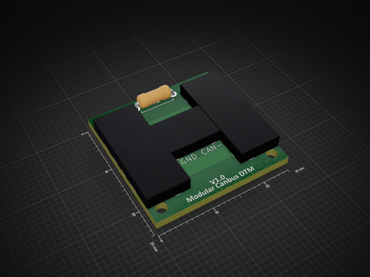
 LoganCarter08/Open_CAN_Bus_Hub13
An open source alternative to a CAN bus hub primarily used in aftermarket automotive industry.
DTM4CanbusPCB Board is an open-source printed circuit board by LoganCarter08, from the LoganCarter08/Open_CAN_Bus_Hub repository on GitHub, published under the MIT licence. It is a 2-layer board of 25 × 25 mm with 4 parts on 4 nets, routed with 36 tracks and 0 vias.
Its parts include 3 ICs and 1 resistor.
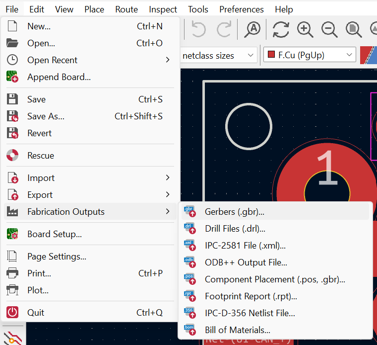
The following is intended to help with ordering and assembly of the PCB.
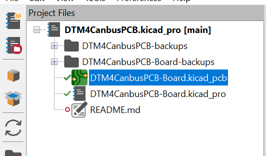
If you plan to modify the PCB or order it from somewhere other than PCBWay you will need KiCad 9.0 or newer.
If you are in the US and looking to place a small order, feel free to contact me as I might have some that I can ship out. Small batch orders of PCBs are generally much more expensive per board than bulk orders.
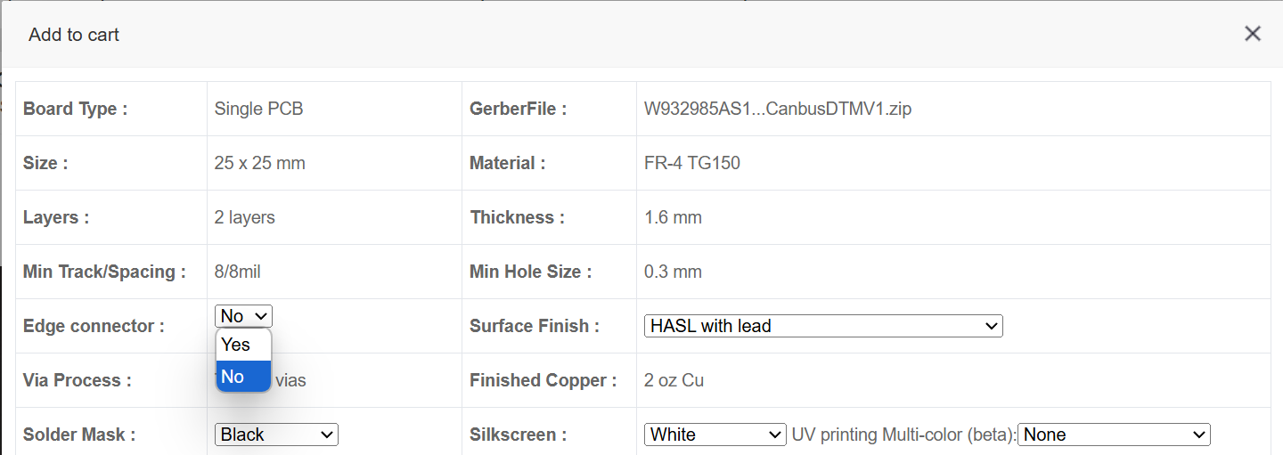
The design has been shared on PCBWay and can be ordered here. My suggestion would be to set the edge connector field to "No" versus the default "Yes". If you do not, it is likely PCBWay will contact you to ask you some details about the edge connection. This is not a normal edge connection and can be handled as a solder pad during manufacturing. From there the rest can be default or any other option you may want.
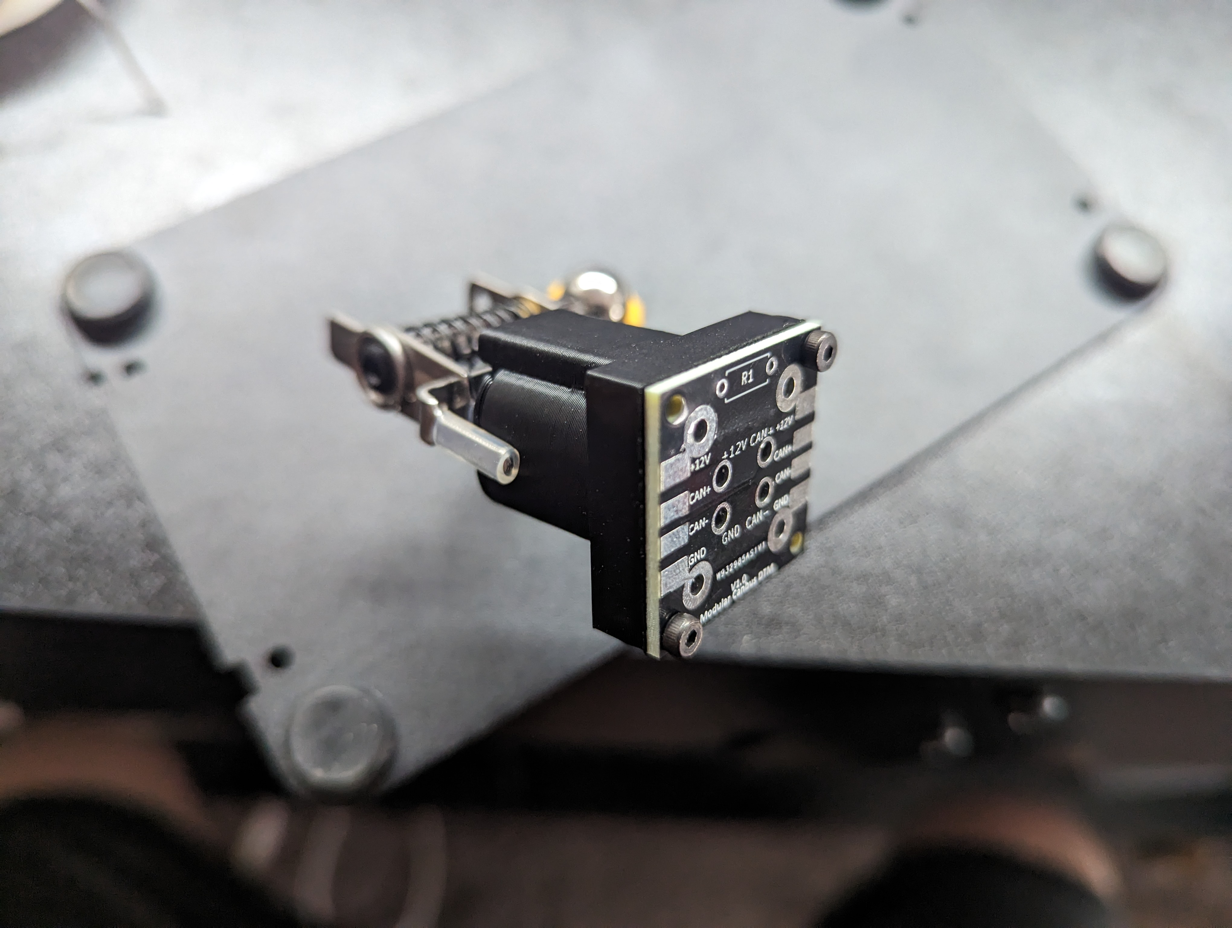
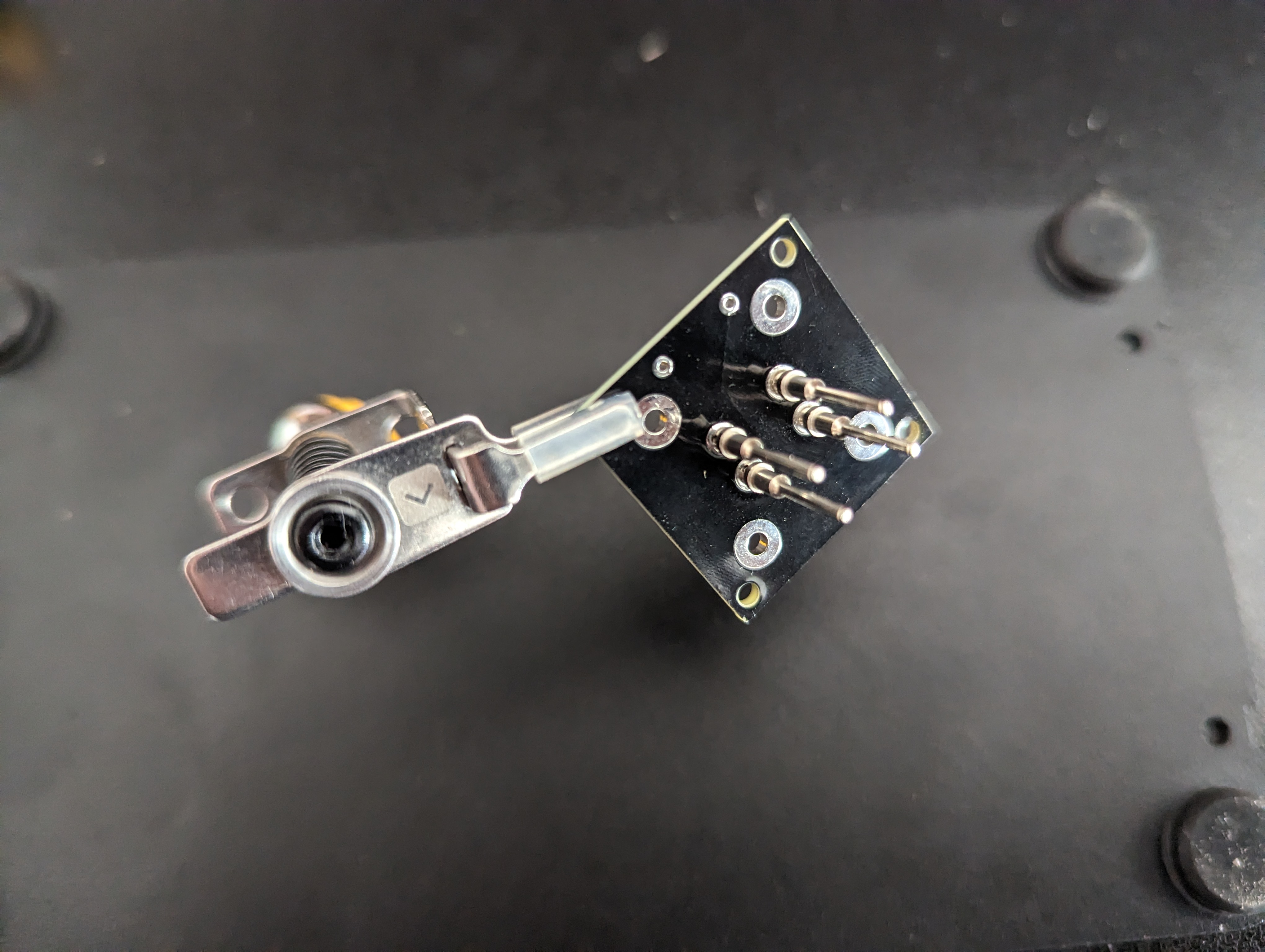
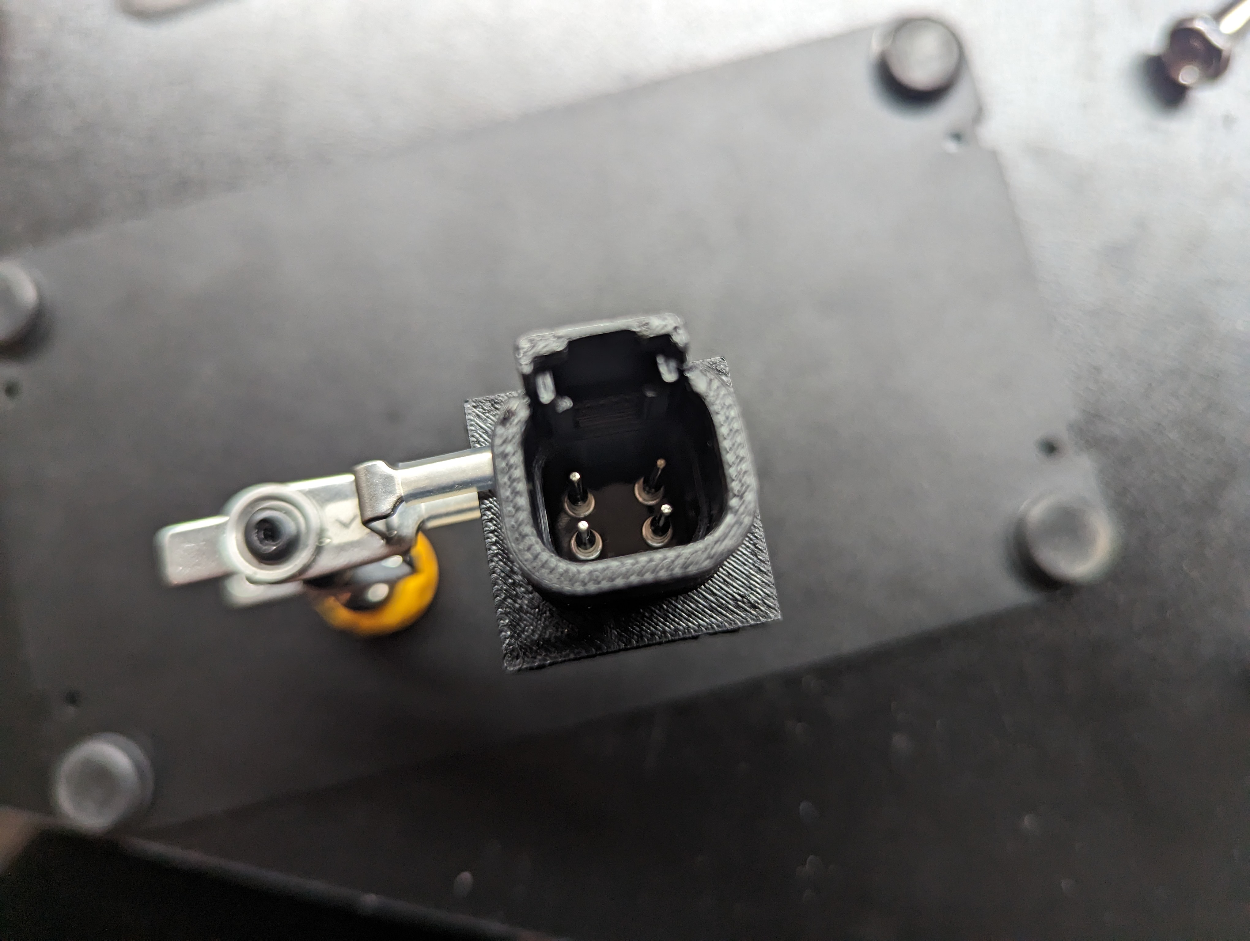
| Qty | Value | Footprint | References |
|---|---|---|---|
| 1 | 120R | Resistor_THT:R_Axial_DIN0207_L6.3mm_D2.5mm_P7.62mm_Horizontal | R1 |
| 1 | ~ | Custom_Footprints:DTM4_CABUS_Pin_Footprint | U5 |
| 1 | ~ | Custom_Footprints:DTM4_CANBUS_Edge_Footprint_Mirrored | U2 |
| 1 | ~ | Custom_Footprints:DTM4_CANBUS_Edge_Footprint | U1 |
joypad-ai/joypad-os
Universal controller firmware for building adapters, dongles, and custom controllers.


hackclub/OnBoard
💡 Join 1,000 teenagers and make your first PCB with a $100 grant!

tardate/LittleArduinoProjects
a collection of "Little Electronic & Arduino Projects", most involving electronics or an Arduino in one way or another!

drandyhaas/KiCadRoutingTools
A set of Python/Rust tools to aid routing in KiCad

osy/XG_Mobile_Station
Open source eGPU dock for ROG Ally and ROG Flow

Luos-io/luos_engine
Open-source and real-time orchestrator for cyber-physical-systems, to easily design, test and deploy embedded applications and digital twins.

NVNTLabs/switch2-SDEX2M2
Micro SD Express to M.2 NVME Adapter for Nintendo Switch 2
It measures 25 × 25 mm and has 2 copper layers, 1.6 mm thick.
4 parts. The full list of its parts is on this page, with links to each part's symbol and footprint where PCBKit's library has them.
From the LoganCarter08/Open_CAN_Bus_Hub repository on GitHub, at the commit this page was made from: the board is PCB/DTM4CanbusPCB-Board.kicad_pcb and its schematic PCB/DTM4CanbusPCB-Schematic.kicad_sch. PCBKit opens the board in the browser, with nothing to install.
Its repository publishes it under the MIT licence: you may reuse it on that licence's terms (keep the author's notice, and for a copyleft licence share your changes alike).