2 layers133.1 × 79.2 mm
Videoslotadapter
LinuxJedi/AmigaRGBtoHDMI
LinuxJedi's designs for Amiga RGBtoHDMI boards.
20 parts127GPL-3.0

 LinuxJedi/AmigaRGBtoHDMI127
LinuxJedi's designs for Amiga RGBtoHDMI boards.
Videoslotadapter is an open-source printed circuit board by LinuxJedi, from the LinuxJedi/AmigaRGBtoHDMI repository on GitHub, published under the GPL-3.0 licence. It is a 2-layer board of 152 × 57.6 mm with 22 parts on 113 nets, routed with 344 tracks and 72 vias.
It is built around the 74LVC574AD, 74LVC86AD and TLV74333PDBVR-TP. Its parts include 7 capacitors, 5 ICs and 2 resistors. It belongs with the retro computing and games boards of this library.


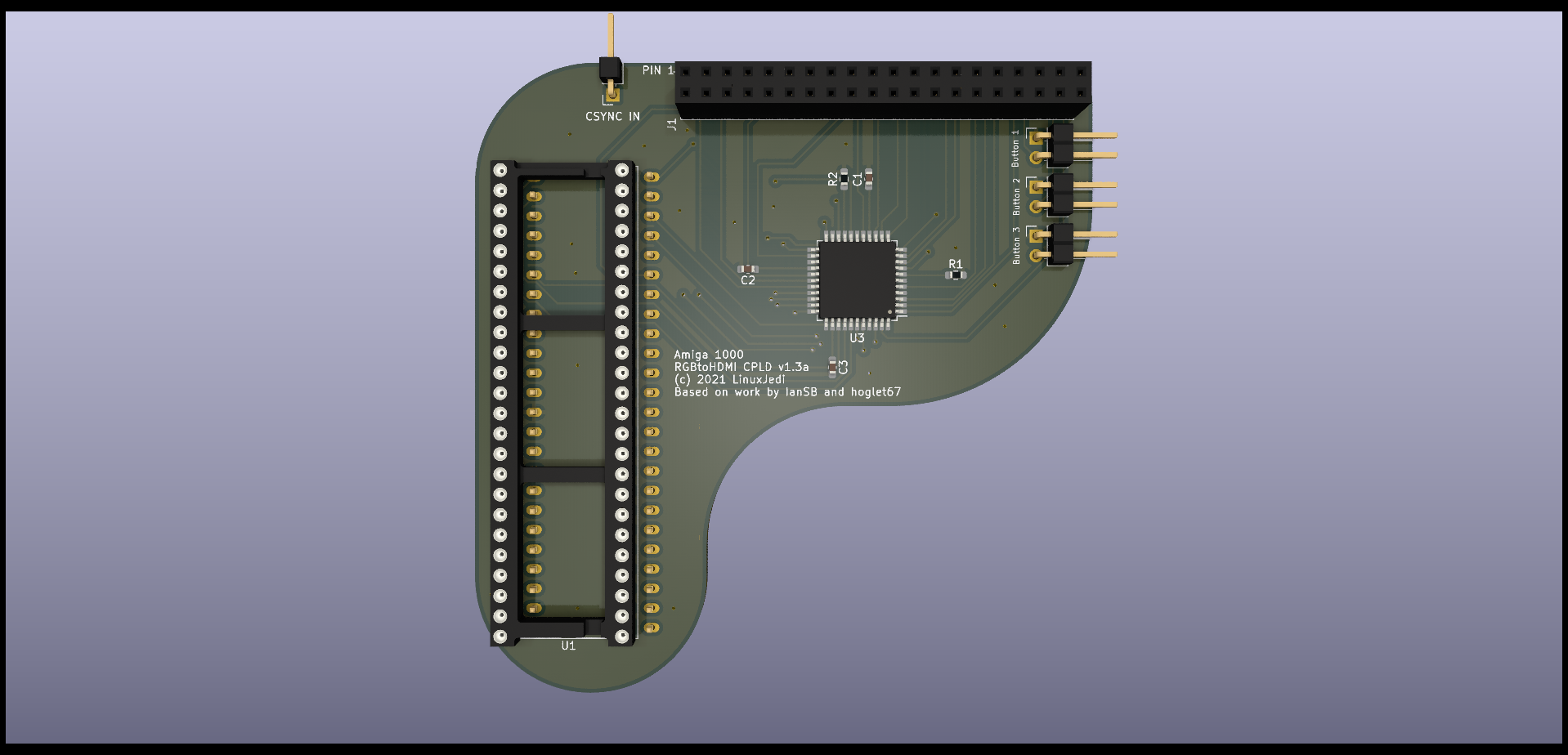
This adaptor uses a CPLD to pass the RGB and sync signals from the Amiga 1000 Denise socket to the Rasperry Pi Zero. It derives the pixel clock in a very different way to other designs and therefore does not require a jumper for Denise / Super Denise and has no "sparkling" pixel issues. It also has the advantage of being firmware upgradable if there are any issues found in the logic.
NOTE: There is an error in v1.1 boards, the text starting "IF YOU CAN READ THIS" is on the wrong side and shoud not be covered up by the Pi. The Pi goes outwards from the board.
ATTENTION PI Zero 2W users: You can now use a Pi Zero 2W with the CPLD RGBtoHDMI using the December 24th 2021 release.
| Symbol | Component |
|---|---|
| C1, C2, C3 | 0.1uF 0603 |
| J1 | 2x20pin socket 2.54mm |
| J2 | 1pin right angle header 2.54mm |
| JButton1 - 3 | 2pin right angle header 2.54mm |
| R1 | 1K 0603 |
| R2 | 4.7K 0603 |
| U1 | 48pin DIP socket 2.54mm |
| U2 | 2x24pin SILs machined pins 2.54mm |
| U3 | XC9572XL 44pin QFP |
NOTE: If you have a Rejouvenator in your Amiga 1000, this patches the CSYNC and you don't need a patch wire, using the CSYNC pin can cause sync issues with a Rejouvenator.
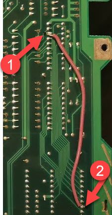
The Amiga 1000 does not have CSYNC wired to Denise. There are two ways around this, the first is to wire CSYNC to the Denise socket on the motherboard using a patch wire. This is pin 8 of UA6 to pin 32 of Denise as below:
Alternatively you can use the "CSYNC IN" on the RGB to HDMI board to hook onto the relevant CSYNC signal. This is pin 8 or UA6 as can be seen below (for both PAL and NTSC):
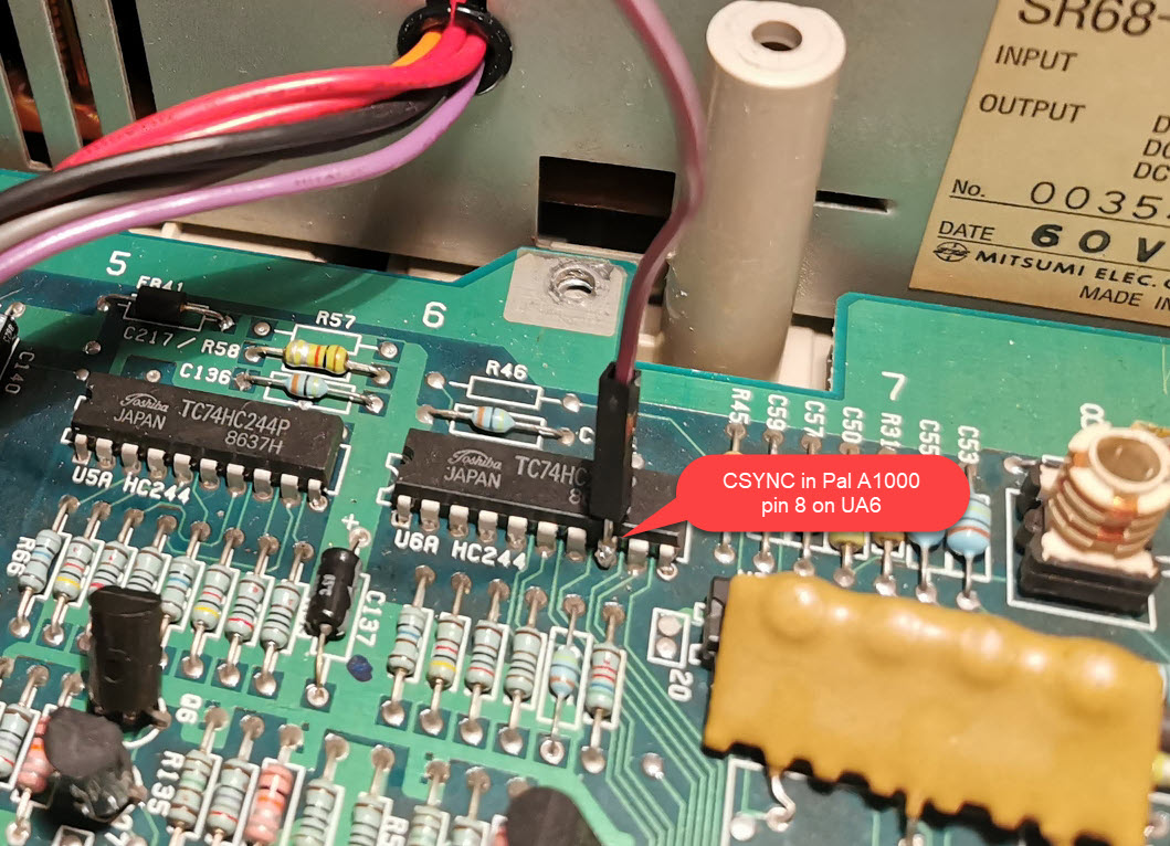
Thanks to @SirCathal for the above two photos.
The software on the Pi should be at least the latest 20210529 release from the main tree or the latest IanSB beta release extracted onto a micro SD card in FAT32 format.
You need to copy some canned profile files into place for the board:
Amiga_CPLD_Readme/Amiga_CPLD_Setup/profile_6-12_BIT_RGB.txt to the root of the SD cardAmiga_CPLD_Readme/Amiga_CPLD_Setup/Profiles/Default.txt to the Profiles directoryThis resolves some issues with mode switching, particularly on NTSC machines. The profile copied will automatically set single_button_mode.
The CPLD will need flashing with the 6-12_BIT_RGB_CPLD firmware. The other firmware options are not compatible with the profiles.
If you have followed the software steps above you will get a recovery menu, select 6-12_BIT_RGB_CPLD, confirm and the Pi will flash the CPLD and reboot.
You may see a shimmer or wavy effect. This is because the phase is set incorrectly and needs calibration, this is a one-off easy thing to do. If you have a static image such as the Kickstart 1.3 boot screen or Workbench with no mouse movement you can use the "Auto Calibrate Video Settings" option (it will require you to select twice to activate). Alternatively you can go into the "Sampling" menu and change the "Sampling Phase" until the image looks correct. Typically 0, 3 or 5 will work fine, but it could be different in each machine.
Once calibrated choose "Save Configuration" and this will be remembered for subsequent boots.
I've made the PCBs available on PCBWay here.
Assembled boards are also available from me on Tindie.
| Qty | Value | Footprint | References |
|---|---|---|---|
| 4 | 100nF | Capacitor_SMD:C_0603_1608Metric_Pad1.08x0.95mm_HandSolder | C1, C2, C3, C7 |
| 2 | 1uF | Capacitor_SMD:C_0805_2012Metric_Pad1.18x1.45mm_HandSolder | C4, C5 |
| 2 | 74LVC574 | Package_SO:TSSOP-20_4.4x6.5mm_P0.65mm | U2, U3 |
| 2 | 74LVC86 | Package_SO:TSSOP-14_4.4x5mm_P0.65mm | U1, U5 |
| 2 | Conn_01x02 | Connector_PinHeader_2.54mm:PinHeader_1x02_P2.54mm_Horizontal | JButton1, JButton2 |
| 1 | 0R | Resistor_SMD:R_0603_1608Metric_Pad0.98x0.95mm_HandSolder | R2 |
| 1 | 3k3 | Resistor_SMD:R_0805_2012Metric_Pad1.20x1.40mm_HandSolder | R1 |
| 1 | A2000_Video_Slot_Phys | amiga-conn:A2000_Video_Slot | JVideoSlot1 |
| 1 | Conn_02x20_Odd_Even | Connector_PinSocket_2.54mm:PinSocket_2x20_P2.54mm_Vertical | JRaspberryPiZero1 |
| 1 | Jumper_3_Bridged12 | Jumper:SolderJumper-3_P1.3mm_Open_Pad1.0x1.5mm | JP2 |
| 1 | Jumper_3_Bridged12 | Connector_PinHeader_2.54mm:PinHeader_1x03_P2.54mm_Horizontal | JP1 |
| 1 | NC | Capacitor_SMD:C_0603_1608Metric_Pad1.08x0.95mm_HandSolder | C6 |
| 1 | TLV74333PDBVR | Package_TO_SOT_SMD:SOT-23-5_HandSoldering | U4 |
The 20 most common of 22 parts.
LinuxJedi/AmigaRGBtoHDMI
LinuxJedi's designs for Amiga RGBtoHDMI boards.

LinuxJedi/AmigaRGBtoHDMI
LinuxJedi's designs for Amiga RGBtoHDMI boards.

LinuxJedi/AmigaRGBtoHDMI
LinuxJedi's designs for Amiga RGBtoHDMI boards.


hoglet67/RGBtoHDMI
Bare-metal Raspberry Pi project that provides pixel-perfect sampling of Retro Computer RGB/YUV video and conversion to HDMI


jasonsbeer/Amiga-HDMI-Through-Hole
Amiga Video Slot to HDMI Adapter


robfinch/Cores
Cores ===== RTF's Cores Use at your own risk. Welcome to my galaxy of cores. Contained in the directories are IP cores, source code for digital circuits.
It measures 152 × 57.6 mm and has 2 copper layers, 1.6 mm thick.
22 parts, built around the 74LVC574AD, 74LVC86AD and TLV74333PDBVR-TP. The full list of its parts is on this page, with links to each part's symbol and footprint where PCBKit's library has them.
From the LinuxJedi/AmigaRGBtoHDMI repository on GitHub, at the commit this page was made from: the board is Legacy/Amiga2000Slot/videoslotadapter.kicad_pcb and its schematic Amiga2000CPLDSlot/videoslotadapter.kicad_sch. PCBKit opens the board in the browser, with nothing to install.
Its repository publishes it under the GPL-3.0 licence: you may reuse it on that licence's terms (keep the author's notice, and for a copyleft licence share your changes alike).