2 layers96.7 × 66.4 mm
Stepper analyzer
zapta/legacy_stepper_motor_analyzer
A DYI minimalist hardware stepper motor analyzer with graphical touch screen.
32 parts162CC0-1.0

 Lasanyan/AtariVGA1
VGA to Atari CRT adapter
Atari adapter is an open-source printed circuit board by Lasanyan, from the Lasanyan/AtariVGA repository on GitHub. It is a 4-layer board of 86 × 33.5 mm with 41 parts on 37 nets, routed with 270 tracks and 40 vias.
It is built around the LM324, M24C02-FMN6P and SDF-130J. Its parts include 9 connectors, 5 resistors, 4 capacitors and 2 ICs. It belongs with the retro computing and games and interfaces and adapters boards of this library.


Converts VGA signals to the 13-pin DIN connector used by Atari SM/ST Series Monochrome CRT Monitors
[!IMPORTANT] Some adapters will refuse to set a mode and send signals if it doesn't receive an EDID from the connected display. To provide an EDID you need to either connect a VGA monitor via the passthrough port or install and flash the 24C02 EEPROM with a valid EEPROM, preferably matching your monitor's specs as close as possible. Then use tools like
xrandrto refine your VGA timings.
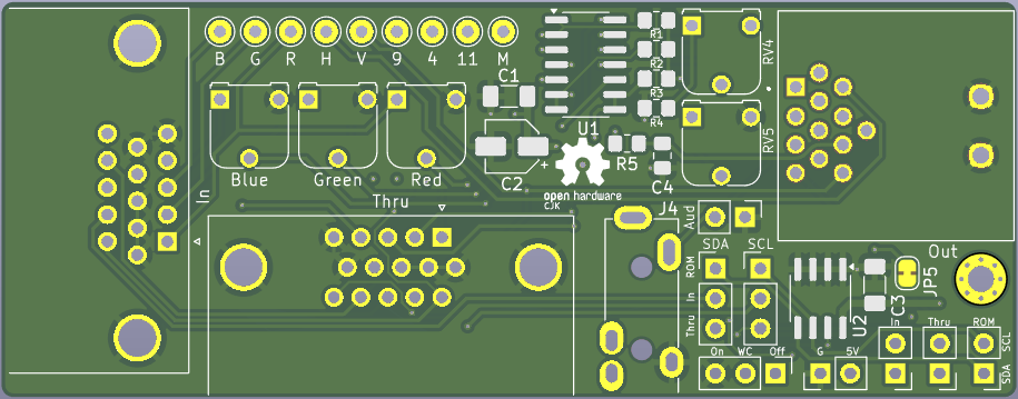
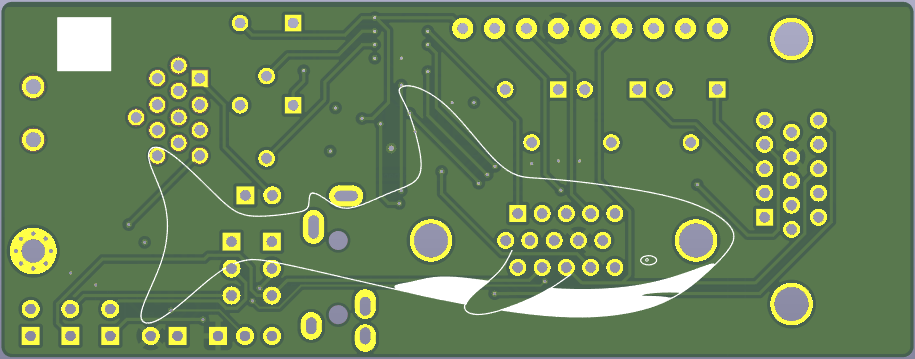
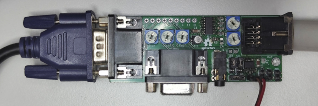
| Qty | Value | Footprint | References |
|---|---|---|---|
| 9 | TestPoint | Connector_Pin:Pin_D1.0mm_L10.0mm | TP1, TP2, TP3, TP4, TP5, TP6, TP7, TP8, TP9 |
| 5 | Conn_01x02 | Connector_PinHeader_2.54mm:PinHeader_1x02_P2.54mm_Vertical | J5, J8, J9, J10, J11 |
| 3 | 100R | Potentiometer_THT:Potentiometer_Runtron_RM-065_Vertical | RV1, RV2, RV3 |
| 3 | 2.2k | Resistor_SMD:R_0805_2012Metric_Pad1.20x1.40mm_HandSolder | R1, R2, R3 |
| 2 | 100n | Capacitor_SMD:C_1206_3216Metric_Pad1.33x1.80mm_HandSolder | C1, C3 |
| 2 | 10k | Potentiometer_THT:Potentiometer_Runtron_RM-065_Vertical | RV4, RV5 |
| 2 | DE15_Socket_HighDensity_MountingHoles | Connector_Dsub:DSUB-15-HD_Socket_Horizontal_P2.29x2.54mm_EdgePinOffset8.35mm_Housed_MountingHolesOffset10.89mm | J1, J2 |
| 2 | Jumper_3_Open | Connector_PinHeader_2.54mm:PinHeader_1x03_P2.54mm_Vertical | JP3, JP4 |
| 1 | 10u | Capacitor_SMD:CP_Elec_4x5.4 | C2 |
| 1 | 3.3k | Resistor_SMD:R_0805_2012Metric_Pad1.20x1.40mm_HandSolder | R4 |
| 1 | AudioJack2 | NyaLib:Jack_3.5mm_CUI_SJ-3524-THT_Horizontal | J4 |
| 1 | C | Capacitor_SMD:C_0805_2012Metric_Pad1.18x1.45mm_HandSolder | C4 |
| 1 | Jumper_3_Bridged12 | Connector_PinHeader_2.54mm:PinHeader_1x03_P2.54mm_Vertical | JP1 |
| 1 | LM324 | Package_SO:SOIC-14_3.9x8.7mm_P1.27mm | U1 |
| 1 | M24C02-FMN | Package_SO:SOIC-8_3.9x4.9mm_P1.27mm | U2 |
| 1 | R | Resistor_SMD:R_0805_2012Metric_Pad1.20x1.40mm_HandSolder | R5 |
| 1 | SDF-130J | NyaLib:CUI_SDF-130J | J3 |
| 1 | SolderJumper_2_Bridged | Jumper:SolderJumper-2_P1.3mm_Bridged_RoundedPad1.0x1.5mm | JP5 |
The 38 most common of 41 parts.
zapta/legacy_stepper_motor_analyzer
A DYI minimalist hardware stepper motor analyzer with graphical touch screen.


YC-Lam/simple_CM4_cluster
Raspbberry Pi compute module 4 cluster in a 120x120x60mm form-factor. each pi can work alone as a 78x58mm SBC

Bogdan8266/h616-board
8-layer Allwinner H616/618 SBC with DDR3, USB, Wi-Fi/BT and battery power support, designed for embedded Linux.


atop8918/DigitalWaters_WD_prototype
Simplified Schematic for prototype release

It measures 86 × 33.5 mm and has 4 copper layers, 1.6 mm thick.
41 parts, built around the LM324, M24C02-FMN6P and SDF-130J. The full list of its parts is on this page, with links to each part's symbol and footprint where PCBKit's library has them.
From the Lasanyan/AtariVGA repository on GitHub, at the commit this page was made from: the board is atari_adapter.kicad_pcb and its schematic atari_adapter.kicad_sch. PCBKit opens the board in the browser, with nothing to install.
Its repository states no licence, so its author keeps all rights: ask Lasanyan before reusing the design.