

2 layers33.7 × 97.8 mm
HAN ESP TSS721
UtilitechAS/amsreader-firmware
ESP8266 and ESP32 compatible firmware to read, interpret and publish data to MQTT from smart electrical meters, both DLMS and DSMR is supported
29 parts470

ROS2‑based platform designed to streamline the development and deployment of autonomous mobile robots.
UPD PCB is an open-source printed circuit board by Lapland-Robotics, from the Lapland-Robotics/AI.R-Autonomous_Robot repository on GitHub, published under the MIT licence. It is a 6-layer board of 145 × 65 mm with 152 parts on 66 nets, routed with 400 tracks and 245 vias.
It is built around the BSS84. Its parts include 54 resistors, 41 capacitors, 12 connectors, 8 ICs and 8 diodes. It belongs with the robots and motor control boards of this library.

This is a modular, ROS2‑based platform designed to streamline the development and deployment of autonomous mobile robots. At its core, it leverages ROS2 Navigation 2 for robust path planning and obstacle avoidance, integrates a flexible sensor suite (Lidar, Stereo camera, Thermal camera, GNSS module, ultrasonic array) for reliable perception, and employs Docker containers to ensure reproducible builds. From low‑level firmware on ESP32 microcontrollers to high‑level controls on an NVIDIA Jetson.
This section outlines the main directory structure of the project, separating documents, firmware, hardware designs, and ROS2-based software to keep development organized and modular.
├── Documents           # All the Documents and Diagrams
│   ├── MiniATV         # Documents about mini ATV
│   └── Snower          # Documents about Snower
├── Firmware            # All the Firmware programs (for Micro controllers)
├── Hardware            # Universal PCB Design and implementation
├── README.md           # main README file
└── Software # ROS2 project for Main Brain(Jetson) of the Robots 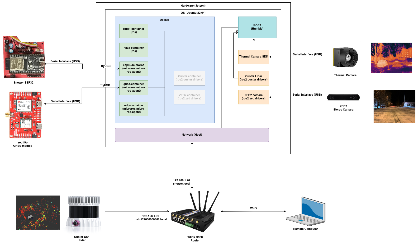
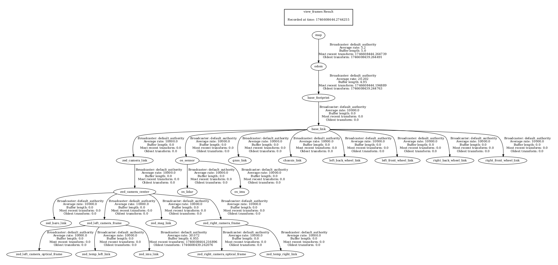
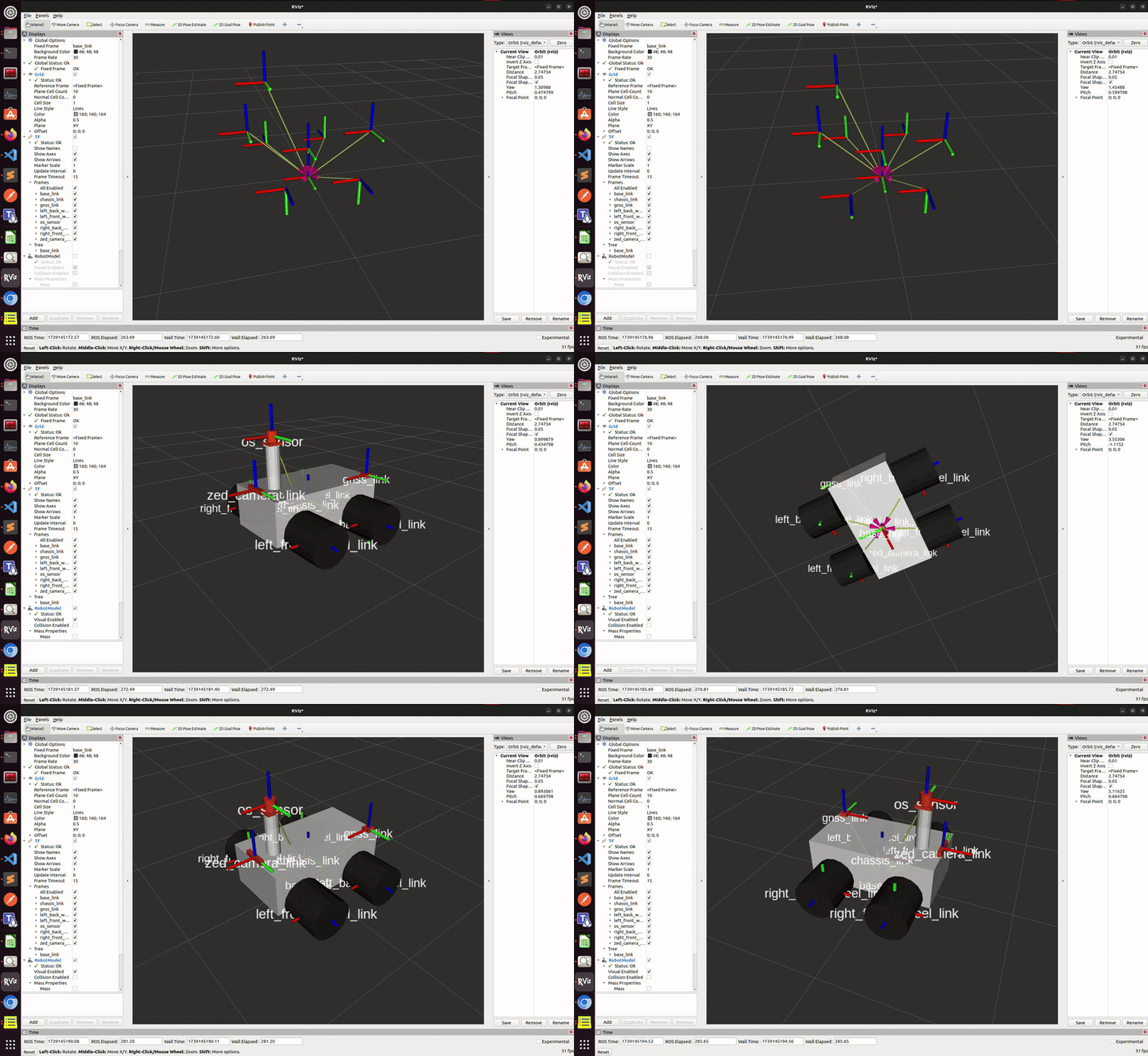
The robot uses a structured TF (transform) tree to manage spatial relationships between all its components, including sensors, base links, and actuators. This hierarchy ensures that data from various sources—like lidar, camera, and GNSS—can be accurately fused and interpreted in a common coordinate space. The TF tree below visualizes how frames are connected and updated in real time during operation.
The ROS2 system is composed of multiple nodes that communicate through a network of topics to handle various tasks like localization, navigation, perception, and control. Each node is modular and focused on a specific function
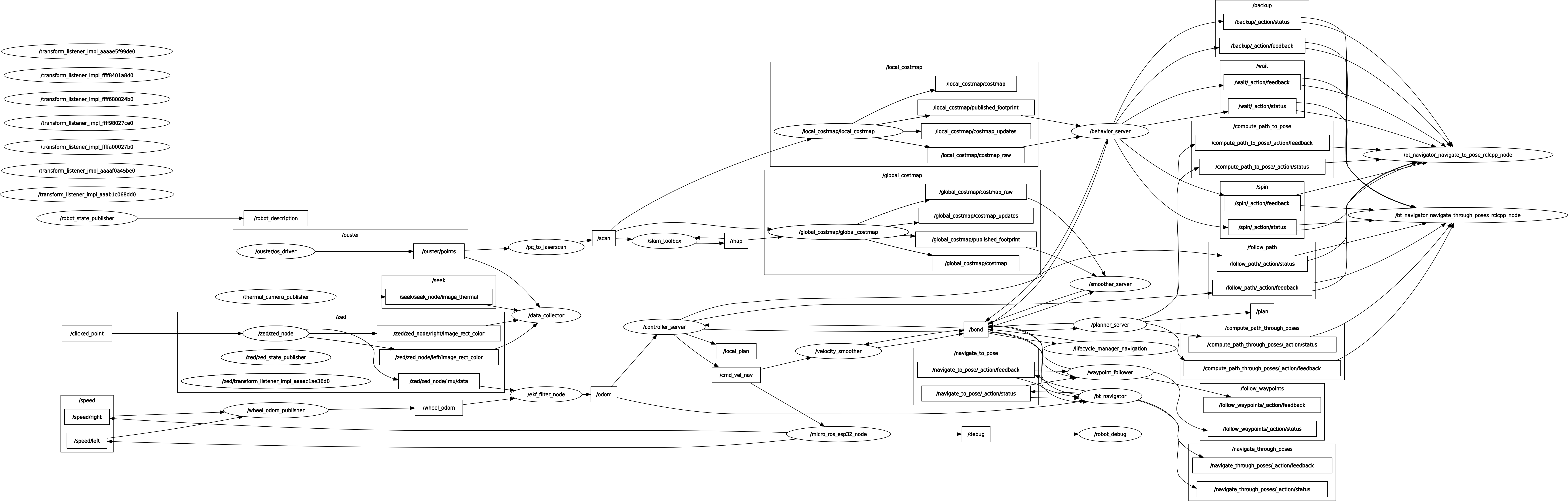
This diagram, generated with rqt_graph, illustrates the live connections between all ROS2 nodes and topics in the Snower. It shows how sensor publishers (e.g., lidar, camera, GNSS, odometry) feed into processing and filtering nodes, how planners and behavior servers interact via action servers/topics, and how control commands flow down to the motor drivers and micro-ROS bridge on the ESP32. By visualizing the full publisher–subscriber and action-server network, you can more verify how each node is wired into the overall autonomy pipeline.
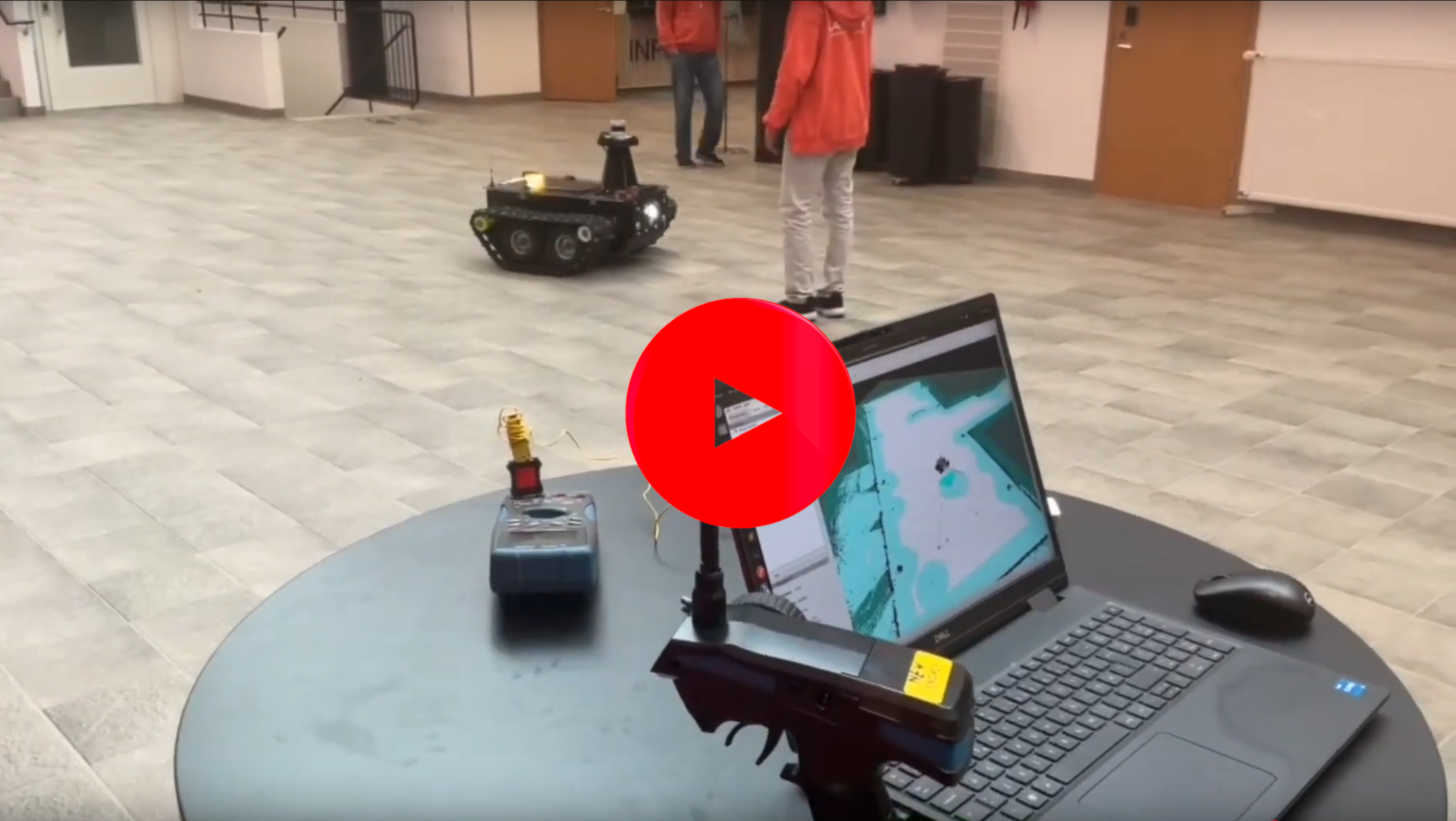
Click the thumbnail below to watch the demo video:
| Qty | Value | Footprint | References |
|---|---|---|---|
| 20 | 0.1µF | Capacitor_SMD:C_0603_1608Metric_Pad1.08x0.95mm_HandSolder | C14, C15, C23, C24, C28, C29, C30, C31, C32, C33, C34, C35, C36, C37, C38, C39 +4 |
| 14 | 10k | Resistor_SMD:R_0603_1608Metric_Pad0.98x0.95mm_HandSolder | R21, R22, R24, R25, R32, R33, R34, R35, R42, R43, R44, R45, R53, R54 |
| 12 | R50 | Resistor_SMD:R_0603_1608Metric_Pad0.98x0.95mm_HandSolder | R15, R16, R17, R18, R28, R29, R30, R31, R38, R39, R40, R41 |
| 8 | LED | LED_SMD:LED_0603_1608Metric_Pad1.05x0.95mm_HandSolder | D1, D2, D3, D4, D5, D6, D7, D8 |
| 8 | TestPoint | TestPoint:TestPoint_THTPad_D1.0mm_Drill0.5mm | TP1, TP2, TP3, TP4, TP5, TP6, TP7, TP8 |
| 6 | 0.1R | Library:R_shunt_different_pad_layout | R13, R14, R26, R27, R36, R37 |
| 6 | 10k2 | Resistor_SMD:R_0603_1608Metric_Pad0.98x0.95mm_HandSolder | R1, R2, R5, R6, R9, R10 |
| 6 | 1776119-2 | Library:17761192 | J4, J5, J6, J7, J8, J9 |
| 6 | 2.2µF | Capacitor_SMD:C_0603_1608Metric_Pad1.08x0.95mm_HandSolder | C1, C2, C10, C11, C19, C20 |
| 6 | DNP | Capacitor_SMD:C_0603_1608Metric_Pad1.08x0.95mm_HandSolder | C3, C4, C12, C13, C21, C22 |
| 6 | INA219AxD | Package_SO:SOIC-8_3.9x4.9mm_P1.27mm | U2, U3, U4, U5, U6, U7 |
| 6 | LMR51635XDDCR | Library:SOT95P280X110-6N | Q1, Q2, Q3, Q4, Q5, Q6 |
| 5 | 22µF | Capacitor_SMD:CP_Elec_6.3x5.8 | C7, C9, C16, C18, C25 |
| 3 | 330 | Resistor_SMD:R_0603_1608Metric_Pad0.98x0.95mm_HandSolder | R23, R51, R52 |
| 3 | 33µH | Library:INDPM140128X650N | L1, L3, L5 |
| 2 | 10µF | Capacitor_SMD:CP_Elec_6.3x5.8 | C8, C17 |
| 2 | 143k | Resistor_SMD:R_0603_1608Metric_Pad0.98x0.95mm_HandSolder | R4, R8 |
| 2 | 1k | Resistor_SMD:R_0603_1608Metric_Pad0.98x0.95mm_HandSolder | R20, R50 |
| 2 | 22µH | Library:INDPM140128X650N | L2, L4 |
| 2 | 33µF | Capacitor_SMD:CP_Elec_6.3x5.8 | C26, C27 |
| 2 | 796739-2 | Library:7967392 | J2, J10 |
| 1 | 0R | Resistor_SMD:R_0603_1608Metric_Pad0.98x0.95mm_HandSolder | R19 |
| 1 | 1.4k | Resistor_SMD:R_0603_1608Metric_Pad0.98x0.95mm_HandSolder | R49 |
| 1 | 1.8k | Resistor_SMD:R_0603_1608Metric_Pad0.98x0.95mm_HandSolder | R48 |
| 1 | 15µH | Library:INDPM140128X650N | L6 |
| 1 | 194k | Resistor_SMD:R_0603_1608Metric_Pad0.98x0.95mm_HandSolder | R11 |
| 1 | 2.2k | Resistor_SMD:R_0603_1608Metric_Pad0.98x0.95mm_HandSolder | R47 |
| 1 | 232k | Resistor_SMD:R_0603_1608Metric_Pad0.98x0.95mm_HandSolder | R7 |
| 1 | 25A Fuse holder | Library:3557-2 | J1 |
| 1 | 295k | Resistor_SMD:R_0603_1608Metric_Pad0.98x0.95mm_HandSolder | R3 |
| 1 | 4k | Resistor_SMD:R_0603_1608Metric_Pad0.98x0.95mm_HandSolder | R46 |
| 1 | 53k5 | Resistor_SMD:R_0603_1608Metric_Pad0.98x0.95mm_HandSolder | R12 |
| 1 | ACS711xEXLT-31AB | Sensor_Current:Allegro_QFN-12-10-1EP_3x3mm_P0.5mm | U1 |
| 1 | BSS84 | Package_TO_SOT_SMD:SOT-23 | Q7 |
| 1 | Conn_01x01 | Connector_PinHeader_2.54mm:PinHeader_1x01_P2.54mm_Vertical | J12 |
| 1 | Conn_01x02 | Connector_JST:JST_EH_B2B-EH-A_1x02_P2.50mm_Vertical | J3 |
| 1 | Conn_01x04 | Connector_JST:JST_XA_B04B-XASK-1_1x04_P2.50mm_Vertical | J11 |
| 1 | LOGO | Images:Lapin_amk_logo | G*** |
| 1 | LOGO | Images:lapin_amk_round_logo | G*** |
| 1 | LOGO | Images:explosion_2 | G*** |
| 1 | STS30-DIS | Library:SON50P250X250X100-9N-D | IC1 |
The 147 most common of 152 parts.
UtilitechAS/amsreader-firmware
ESP8266 and ESP32 compatible firmware to read, interpret and publish data to MQTT from smart electrical meters, both DLMS and DSMR is supported


giant-axon/lu.i-neuron-pcb
Lu.i is an electronic neuron circuit mimicking and illustrating the basic dynamics of real, biological neurons. The printed circuit board (PCB) features a configurable, fully analog implementation of the leaky…

antmicro/snapdragon-845-baseboard
https://antmicro.com/blog/2022/04/open-source-snapdragon-845-baseboard/

7west/PicoTop
A very basic computer & OS based on the RP2350 microcontroller


It measures 145 × 65 mm and has 6 copper layers, 1.66 mm thick.
152 parts, built around the BSS84. The full list of its parts is on this page, with links to each part's symbol and footprint where PCBKit's library has them.
From the Lapland-Robotics/AI.R-Autonomous_Robot repository on GitHub, at the commit this page was made from: the board is Hardware/UPD_PCB/UPD_PCB.kicad_pcb and its schematic Hardware/UPD_PCB/Block Diagram.kicad_sch. PCBKit opens the board in the browser, with nothing to install.
Its repository publishes it under the MIT licence: you may reuse it on that licence's terms (keep the author's notice, and for a copyleft licence share your changes alike).