
2 layers22 × 18 mm
 LESA-RPI/LESA_OccupancyUnit2
Based on STM's BLEMeshLightingPRFNode example, this project gets data from the ToF and color sensor. Bluetooth functionality has not been fully developed
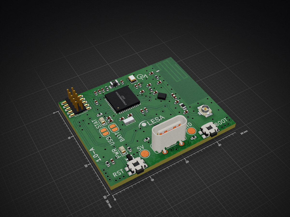
Occupancy Sensor A is an open-source printed circuit board by LESA-RPI, from the LESA-RPI/LESA_OccupancyUnit repository on GitHub, published under the MIT licence. It is a 4-layer board of 36 × 30 mm with 89 parts on 77 nets, routed with 491 tracks and 105 vias.
It is built around the TCS34303, VL53L8CX and ECMF02-2AMX6, with the BSS138 and DMG1012T among its other parts. Its parts include 31 capacitors, 21 resistors, 7 ICs, 6 transistors and 5 inductors. It belongs with the sensors and measurement boards and the STM32 boards of this library.


https://drive.google.com/drive/folders/18Ncf5kQ7dq59xiIikijq2Gq61cseJHMG?usp=sharing
Based on STM's BLE_MeshLightingPRFNode example, this project gets data from the ToF and color sensor. Bluetooth functionality has not been fully developed
graph TD
boot(Initilizaiton of STM32 and task registrations) ---> init(Sensor Init) --wait for init to finish--> standby{Standby};
subgraph Appli_mesh.c & others
standby --sw1 short press--> reply1(BLE color value advertisement);
reply1-->standby
standby --sw1 long press--> reply2(BLE ToF value advertisement);
reply2---> standby
standby --sw2 long press--> base(background set up)---> standby
standby -->change{Color INT}-->sensor(wakes up ToF and data pulling)--No blobs present for long period-->standby
standby --sw2 short press--> loopyloop1(ToF matrix to UART)
loopyloop1--sw2 short press--> standby
endgraph LR
subgraph Room
unit1[Server];unit2[Server];unit3[Server];unit4[Server];unit5{Client};
unit1 & unit2 ---- unit3 & unit4
unit5 ---- unit1
end
unit5 ---- building[Building management sys]Server and Clients are defined by
#define ENABLE_SENSOR_MODEL_SERVER                                           (1)
#define ENABLE_SENSOR_MODEL_CLIENT                                           (0)
, where server is the one with sensor running, and client is the one requesting or listening
graph TD

server[Server]
esp[EPS32]
server <--HTTP--> esp
subgraph Module
stm[STM32] <--UART--> esp
stm <--I2C--> colorsensor[ColorS]
stm <--I2C--> tof[ToF]
end

In order to use this project you must download this entire repository and open the .project file in the STM32CubeIDE folder:
| This is how the files should be placed in the workspace folder | Open the project by clicking the .project file |
The example software provided by ST uses a sequencer library for scheduling tasks.
Before using the sequencer it must be initialized by a call to the function :
UTIL_SEQ_Init( void )
A function is registered as a task in the sequencer by
UTIL_SEQ_RegTask( UTIL_SEQ_bm_t TaskId_bm, uint32_t Flags, void (*Task)( void ) )
The first parameter is the task ID and is a 32-bit value where only one bit should be set, i.e. the maximum number of tasks is 32. The second parameter is not used for anything by the library, and the third parameter is a pointer to the function which should be called when it is time for the task to run.
To request a task to be runned, use function
UTIL_SEQ_SetTask( UTIL_SEQ_bm_t TaskId_bm , uint32_t Task_Prio )
Example:
UTIL_SEQ_Init( void )
UTIL_SEQ_RegTask((1 << 4), UTIL_SEQ_RFU, my_task_function);
UTIL_SEQ_SetTask((1 << 4), CFG_SEQ_Prio_0);This project envisioned using BLE mesh to communicate between units. Click here to learn more.
Tracking_Algo.h Function declerations and Macro settings for STM32
Tracking_Algo.c Algorithm itself, can be copied into an online C compiler to run and test
void link_latest_frame_to_previous(FIFObuffer *fifobuffer) to allow multi-frame tracebackvoid int find_centers_of_mass(int matrix[N][N], Point *center_of_mass) in FrameInfo parse_frame(int matrix[N][N], float deltaX, float deltaY) to allow track person betterapp_tof.c -> /BLE_MeshLightingPRFNode/Application/Core/app_tof.c
- void MX_TOF_Init(void)
: Initialize the TOF sensor. Validates whether it is properly connected and starts the sensor
- static void MX_VL53L8CX_SimpleRanging_Process(void)
: Read and print out the data if the sensor is properly running
- void MX_TOF_ToggleReso(void)
: A public function that calls toggle_resolution. Change the resolution of TOF sensor
You can change the ranging frequency by modifying "RANGING_FREQUENCY" public variable(Set to 20Hz in the code)
*custom_ranging_sensor.c -> /BLE_MeshLightingPRFNode/Application/Core/custom_ranging_sensor.c
- int32_t CUSTOM_RANGING_SENSOR_Start(uint32_t Instance, uint8_t Mode)
: Start the TOF sensor
- int32_t CUSTOM_RANGING_SENSOR_Stop(uint32_t Instance)
: Stop the TOF sensorhttps://github.com/IAmiku/LESA_OccupancyUnit/tree/main/NON-STM32%20Project%20Folder/ESP-TCS3430
TCS3430.h  ->  /BLE_MeshLightingPRFNode/Drivers/BSP/TCS3430/TCS3430.h

- Includes all the address of the registers of TCS3430

- Includes Prototype of functions

- struct tcs3430_optics_val

    : Has X,Y,Z, and IR values

- struct tcs3430

    reginfo -> data in the registers

    XYZinfo -> Low & High byte of X, Y, Z, and IR1

TCS3430.c  ->  /BLE_MeshLightingPRFNode/Drivers/BSP/TCS3430/TCS3430.c

............
Above two functions are necessary whenever you change the setting of the TOF(such as frequency of configure mode)
Reference:
| Qty | Value | Footprint | References |
|---|---|---|---|
| 9 | 100n | Capacitor_SMD:C_0402_1005Metric | C2, C4, C9, C16, C17, C18, C20, C21, C22 |
| 7 | 47K | Resistor_SMD:R_0402_1005Metric | R3, R5, R6, R7, R9, R10, R12 |
| 6 | 1u | Capacitor_SMD:C_0402_1005Metric | C3, C5, C6, C7, C8, C10 |
| 6 | 2.2K | Resistor_SMD:R_0402_1005Metric | R14, R16, R17, R18, R19, R20 |
| 5 | BSS138 | Package_TO_SOT_SMD:SOT-23 | Q1, Q2, Q3, Q4, Q7 |
| 4 | 1K | Resistor_SMD:R_0402_1005Metric | R8, R13, R15, R21 |
| 4 | 4.7u | Capacitor_SMD:C_0402_1005Metric | C1, C13, C15, C19 |
| 3 | 10n | Capacitor_SMD:C_0402_1005Metric | C11, C26, C31 |
| 3 | ~ | Capacitor_SMD:C_0402_1005Metric | C27, C28, C29 |
| 2 | 10p | Capacitor_SMD:C_0402_1005Metric | C12, C14 |
| 2 | 40.2K | Resistor_SMD:R_0402_1005Metric | R4, R11 |
| 2 | 5.1K | Resistor_SMD:R_0402_1005Metric | R1, R2 |
| 1 | 0.3p | Capacitor_SMD:C_0402_1005Metric | C25 |
| 1 | 0.8p | Capacitor_SMD:C_0402_1005Metric | C24 |
| 1 | 0R | Resistor_SMD:R_0603_1608Metric | L4 |
| 1 | 1.2p | Capacitor_SMD:C_0402_1005Metric | C30 |
| 1 | 100p | Capacitor_SMD:C_0402_1005Metric | C23 |
| 1 | 10n | Inductor_SMD:L_0402_1005Metric | L2 |
| 1 | 10u | Inductor_SMD:L_0805_2012Metric | L1 |
| 1 | 2.7n | Inductor_SMD:L_0402_1005Metric | L3 |
| 1 | 3.6n | Inductor_SMD:L_0402_1005Metric | L5 |
| 1 | 5V | TestPoint:TestPoint_Pad_D2.0mm | TP1 |
| 1 | Antenna | Occupancy_Sensor_Custom_Footprints:AN3359_Meander_Antenna | AE1 |
| 1 | BATT | Jumper:SolderJumper-2_P1.3mm_Open_RoundedPad1.0x1.5mm | JP1 |
| 1 | BOOT | Occupancy_Sensor_Custom_Footprints:EVQ-P7A01P | SW1 |
| 1 | Conn_02x05_Odd_Even | Connector_PinHeader_1.27mm:PinHeader_2x05_P1.27mm_Vertical_SMD | J2 |
| 1 | Conn_Coaxial | Occupancy_Sensor_Custom_Footprints:CONUFL001-SMD-T | J3 |
| 1 | DEA162450BT-1295A1 | Occupancy_Sensor_Custom_Footprints:DEA162450BT-1295A1 | U8 |
| 1 | DMG1012T | Package_TO_SOT_SMD:SOT-523 | Q6 |
| 1 | ECMF02-2AMX6 | Package_DFN_QFN:ST_UQFN-6L_1.5x1.7mm_P0.5mm | U3 |
| 1 | GND | TestPoint:TestPoint_Pad_D2.0mm | TP2 |
| 1 | INTC | TestPoint:TestPoint_Pad_D1.0mm | TP7 |
| 1 | INTT | TestPoint:TestPoint_Pad_D1.0mm | TP5 |
| 1 | LOGO | Occupancy_Sensor_Custom_Footprints:LESA_8x4mm | G*** |
| 1 | NX2012_32K768 | Occupancy_Sensor_Custom_Footprints:NX2012_32K768 | Y3 |
| 1 | NX2016SA_32M | Occupancy_Sensor_Custom_Footprints:NX2016SA_32M | Y2 |
| 1 | PWR | LED_SMD:LED_0603_1608Metric | D1 |
| 1 | RST | Occupancy_Sensor_Custom_Footprints:EVQ-P7A01P | SW2 |
| 1 | SCL | TestPoint:TestPoint_Pad_D1.0mm | TP3 |
| 1 | SDA | TestPoint:TestPoint_Pad_D1.0mm | TP4 |
| 1 | STAT | LED_SMD:LED_0603_1608Metric | D2 |
| 1 | STM32WB55CGUx | Package_DFN_QFN:QFN-48-1EP_7x7mm_P0.5mm_EP5.6x5.6mm | U6 |
| 1 | TCS3430 | Occupancy_Sensor_Custom_Footprints:TCS3430 | U5 |
| 1 | TPS7A0318PDBVR | Package_TO_SOT_SMD:SOT-23-5 | U4 |
| 1 | TPS7A0333PDBVR | Package_TO_SOT_SMD:SOT-23-5 | U1 |
| 1 | USB | Jumper:SolderJumper-2_P1.3mm_Bridged_RoundedPad1.0x1.5mm | JP2 |
| 1 | USB_C_Receptacle | Occupancy_Sensor_Custom_Footprints:USB4120-03-C | J4 |
| 1 | VL53L8CX | Occupancy_Sensor_Custom_Footprints:VL53L8CX | U2 |


KOEGlike/meko
A linux music player with ddr3, a 70hz e-paper display and a haptic touchpad

taroz/mosaicHAT-Station
mosaicHAT+ GNSS antenna + Raspberry Pi + Touch display + Battery + Case


It measures 36 × 30 mm and has 4 copper layers, 1.6 mm thick.
89 parts, built around the TCS34303, VL53L8CX, ECMF02-2AMX6 and BSS138. The full list of its parts is on this page, with links to each part's symbol and footprint where PCBKit's library has them.
From the LESA-RPI/LESA_OccupancyUnit repository on GitHub, at the commit this page was made from: the board is Hardware/PCBA/-A/Occupancy_Sensor-A/Occupancy_Sensor-A.kicad_pcb and its schematic Hardware/PCBA/-A/Occupancy_Sensor-A/Antenna.kicad_sch. PCBKit opens the board in the browser, with nothing to install.
Its repository publishes it under the MIT licence: you may reuse it on that licence's terms (keep the author's notice, and for a copyleft licence share your changes alike).