2 layers30 × 61.3 mm
 Kevin-CE21/ESP32-S3-Multimedia-LED-PCB1
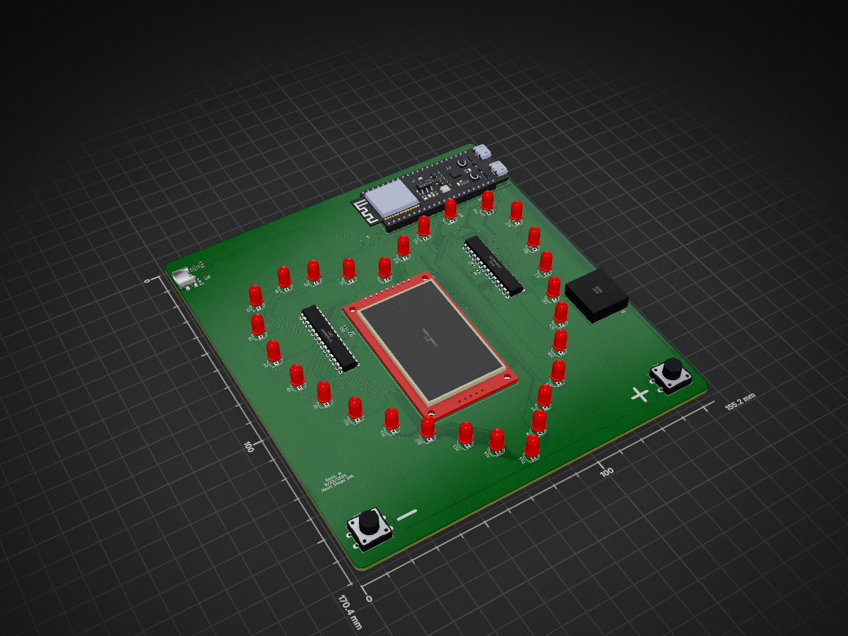
A 2-layer, heart-shaped carrier PCB that combines an ESP32-S3, 28 PWM-dimmed LEDs, a TFT display with microSD, and I2S audio on one USB-C-powered board. Designed from scratch in KiCad, from schematic through layout.
Multimedia LED PCB is an open-source printed circuit board by Kevin-CE21, from the Kevin-CE21/ESP32-S3-Multimedia-LED-PCB repository on GitHub. It is a 2-layer board of 155.2 × 170.3 mm with 45 parts on 86 nets, routed with 817 tracks and 231 vias.
Its parts include 28 diodes, 5 capacitors, 5 ICs, 4 resistors and 2 switches. It belongs with the ESP32 boards of this library.
A 2-layer, heart-shaped carrier PCB that combines an ESP32-S3, 28 PWM-dimmed LEDs, a TFT display with microSD, and I2S audio on one USB-C-powered board. Designed from scratch in KiCad, from schematic through layout.
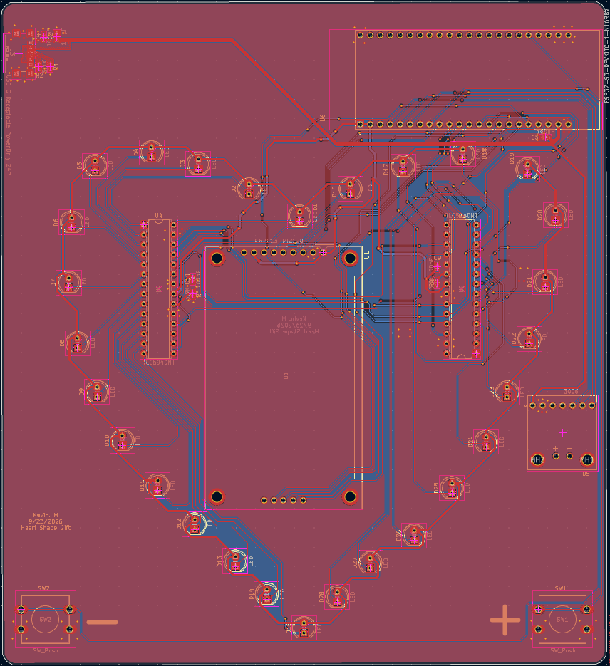
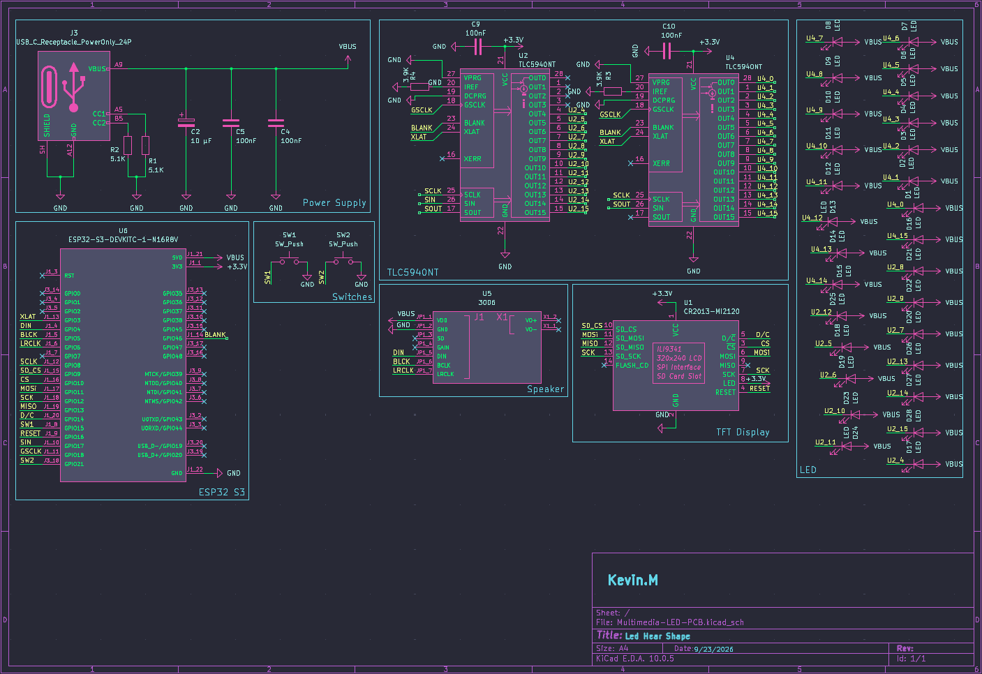
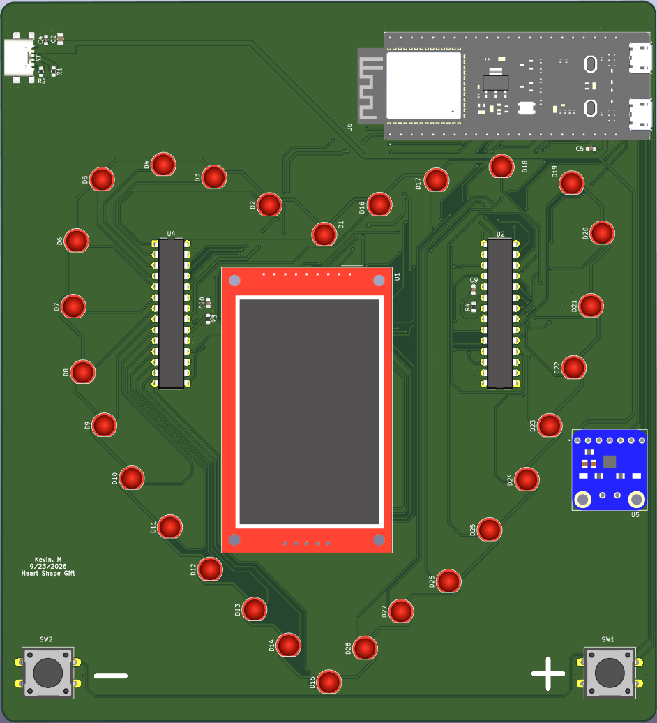
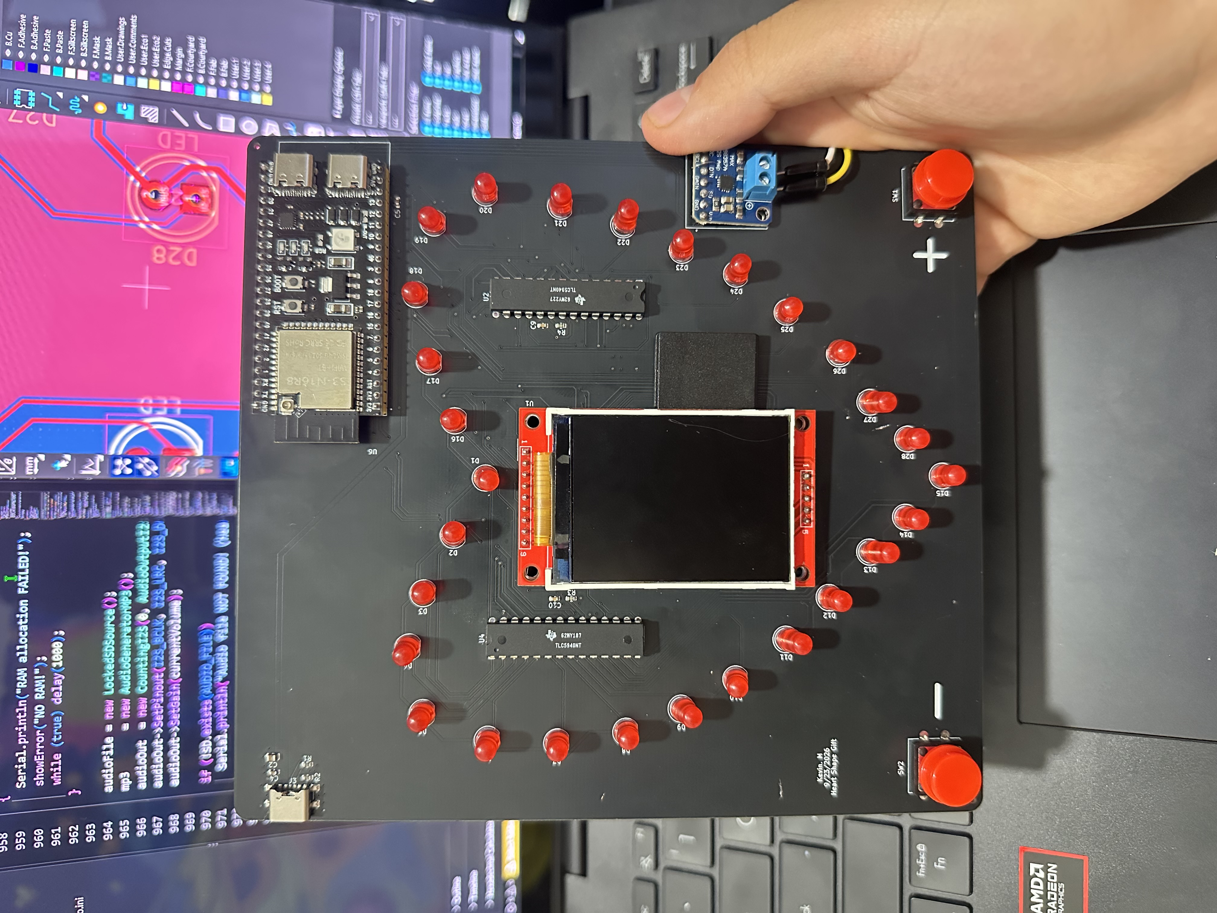
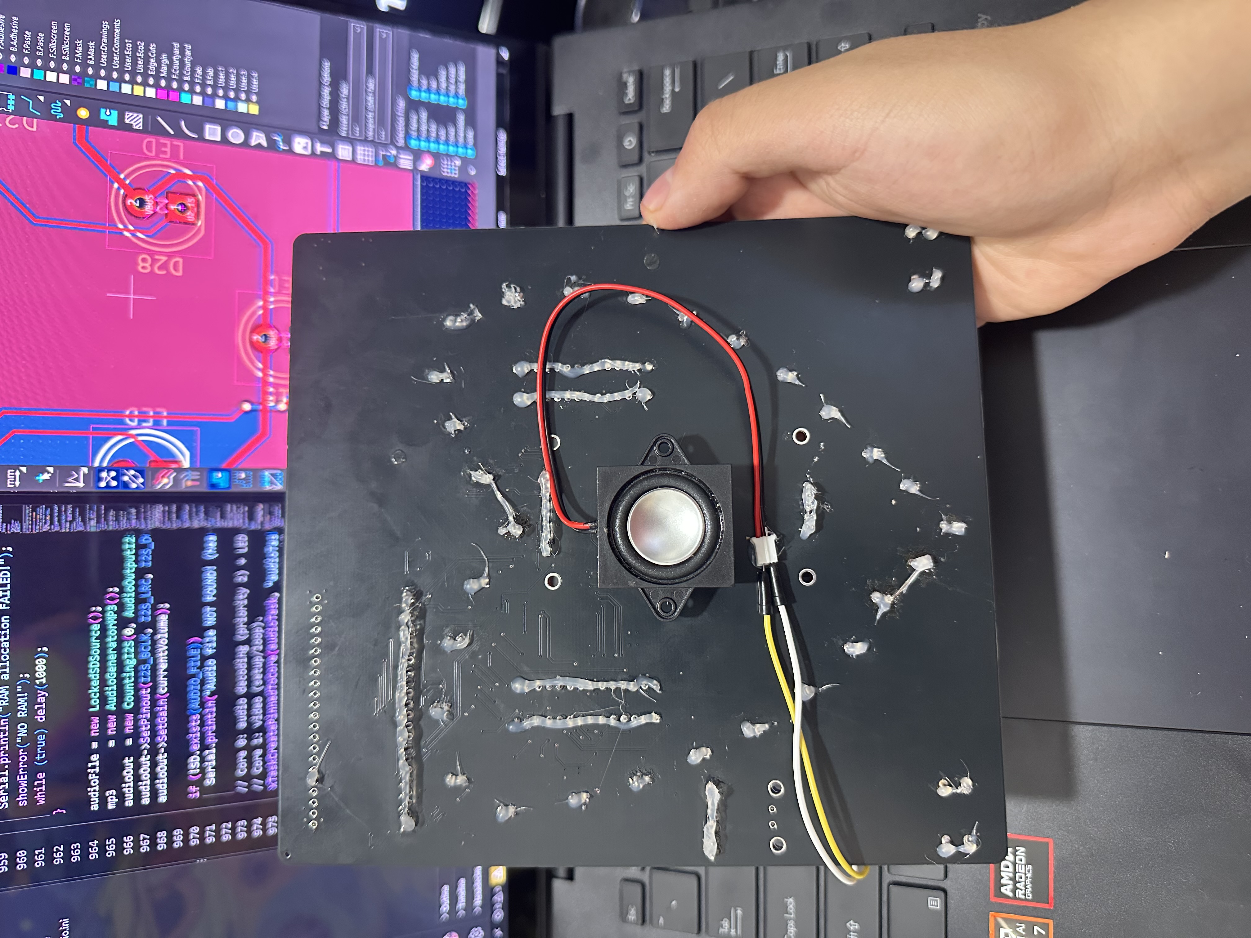
The board is a carrier for an ESP32-S3-DevKitC-1 module. It takes 5 V from a USB-C connector, drives 28 LEDs through two daisy-chained TLC5940 16-channel PWM drivers, shows graphics on an ILI9341 TFT, reads files from that display's microSD slot, and plays audio through a MAX98357A I2S class-D amplifier and speaker. Two pushbuttons provide user input.
| Ref | Part | Role |
|---|---|---|
| U6 | ESP32-S3-DevKitC-1-N16R8V | Microcontroller, Wi-Fi, 3.3 V logic supply |
| U2, U4 | TLC5940NT | 16-channel, 12-bit PWM constant-current LED drivers (daisy-chained) |
| D1–D28 | LEDs | 28 PWM-controlled LEDs |
| U1 | ILI9341 TFT module with microSD | Display and file storage over SPI |
| U5 | MAX98357A (Adafruit 3006) | I2S class-D audio amplifier |
| J3 | USB-C receptacle (power only) | 5 V input |
| R1, R2 | 5.1 kΩ | USB-C CC pull-downs (power sink) |
| R3, R4 | 3.9 kΩ | TLC5940 IREF current-set resistors |
| C4, C5, C9, C10 | 100 nF | Local decoupling |
| C2 | 10 µF | Bulk capacitance |
| SW1, SW2 | Pushbuttons | User input |
Power
LED control
Display and storage
Audio
hardware/SosoGift.kicad_sch: schematichardware/SosoGift.kicad_pro: KiCad project fileimages/: layout, schematic and 3D renders| Qty | Value | Footprint | References |
|---|---|---|---|
| 28 | LED | LED_THT:LED_D5.0mm | D1, D2, D10, D11, D12, D13, D14, D15, D16, D17, D18, D19, D20, D21, D22, D23 +12 |
| 4 | 100nF | Capacitor_SMD:C_0603_1608Metric | C4, C5, C9, C10 |
| 2 | 3.9K | Resistor_SMD:R_0603_1608Metric | R3, R4 |
| 2 | 5.1K | Resistor_SMD:R_0603_1608Metric | R1, R2 |
| 2 | SW_Push | Button_Switch_THT:SW_PUSH-12mm | SW1, SW2 |
| 2 | TLC5940NT | Package_DIP:DIP-28_W7.62mm | U2, U4 |
| 1 | 10 µF | Capacitor_SMD:C_0805_2012Metric | C2 |
| 1 | 3006 | Mine:MODULE_3006 | U5 |
| 1 | CR2013-MI2120 | Display:CR2013-MI2120 | U1 |
| 1 | ESP32-S3-DEVKITC-1-N16R8V | Mine:XCVR_ESP32-S3-DEVKITC-1-N16R8V | U6 |
| 1 | USB_C_Receptacle_PowerOnly_24P | Connector_USB:USB_C_Receptacle_GCT_USB4135-GF-A_6P_TopMnt_Horizontal | J3 |

imchipwood/dumbpad
Simple 4x4 numpad with rotary encoder. Powered by QMK via ATmega32u4 Pro Micro


makeo/PicoLoader
A cheap and easy to install modchip for the Nintendo GameCube!


peterkrull/quad
Firmware, hardware and documentation for my autonomous quad copter project

tebl/RC6502-Apple-1-Replica
An expandable SBC-version of the Apple 1 computer, easy to get started with and lot of cool stuff that can be added to it!

It measures 155.2 × 170.3 mm and has 2 copper layers, 1.6 mm thick.
45 parts. The full list of its parts is on this page, with links to each part's symbol and footprint where PCBKit's library has them.
From the Kevin-CE21/ESP32-S3-Multimedia-LED-PCB repository on GitHub, at the commit this page was made from: the board is Multimedia-LED-PCB.kicad_pcb and its schematic Multimedia-LED-PCB.kicad_sch. PCBKit opens the board in the browser, with nothing to install.
Its repository states no licence, so its author keeps all rights: ask Kevin-CE21 before reusing the design.