
2 layers52.2 × 52.2 mm
Base
google/mozc-devices
Circuit diagrams and firmware source code for Gboard DIY keyboards
43 parts3kApache-2.0

KiCad files for DIY Pro Co RAT
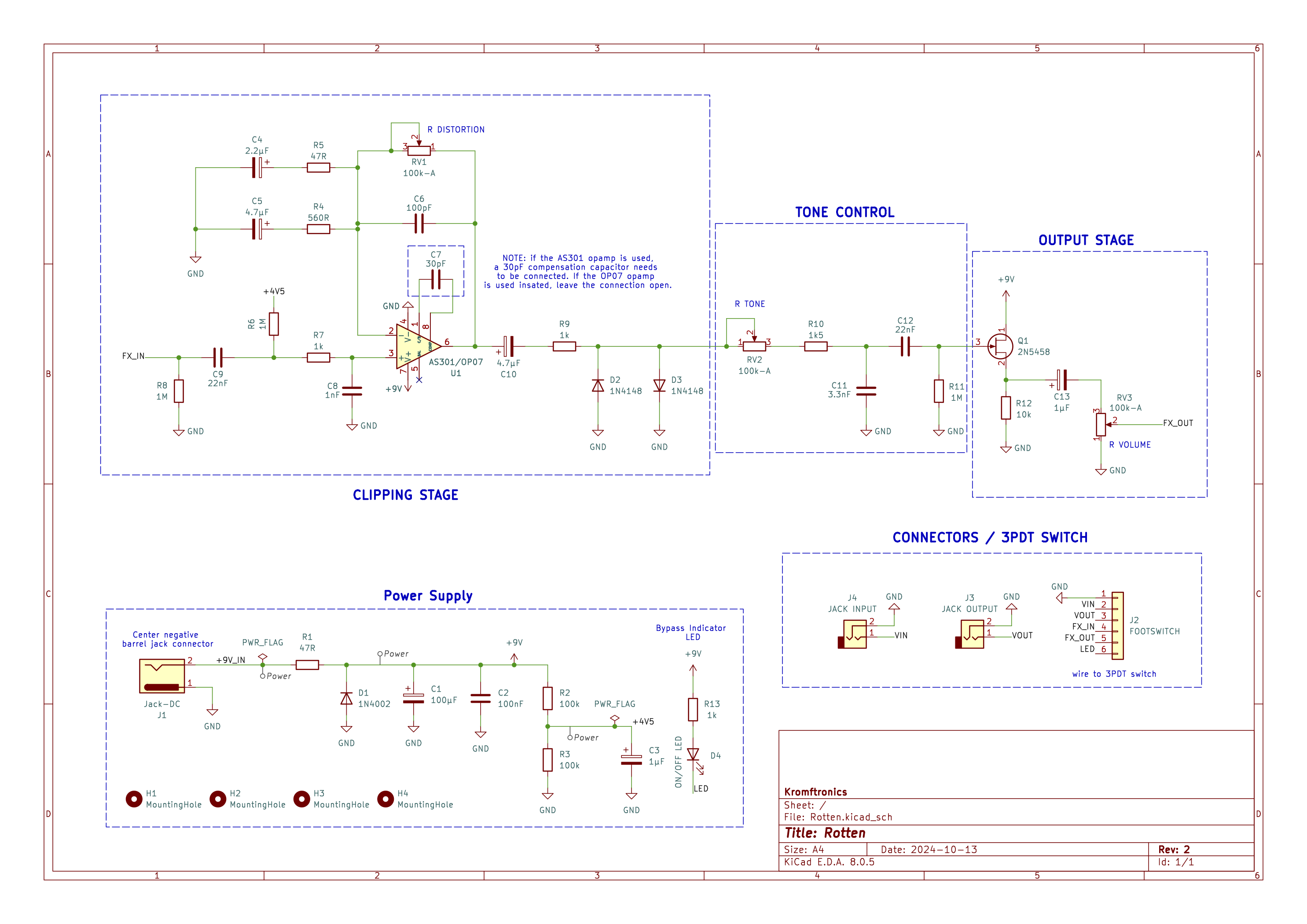
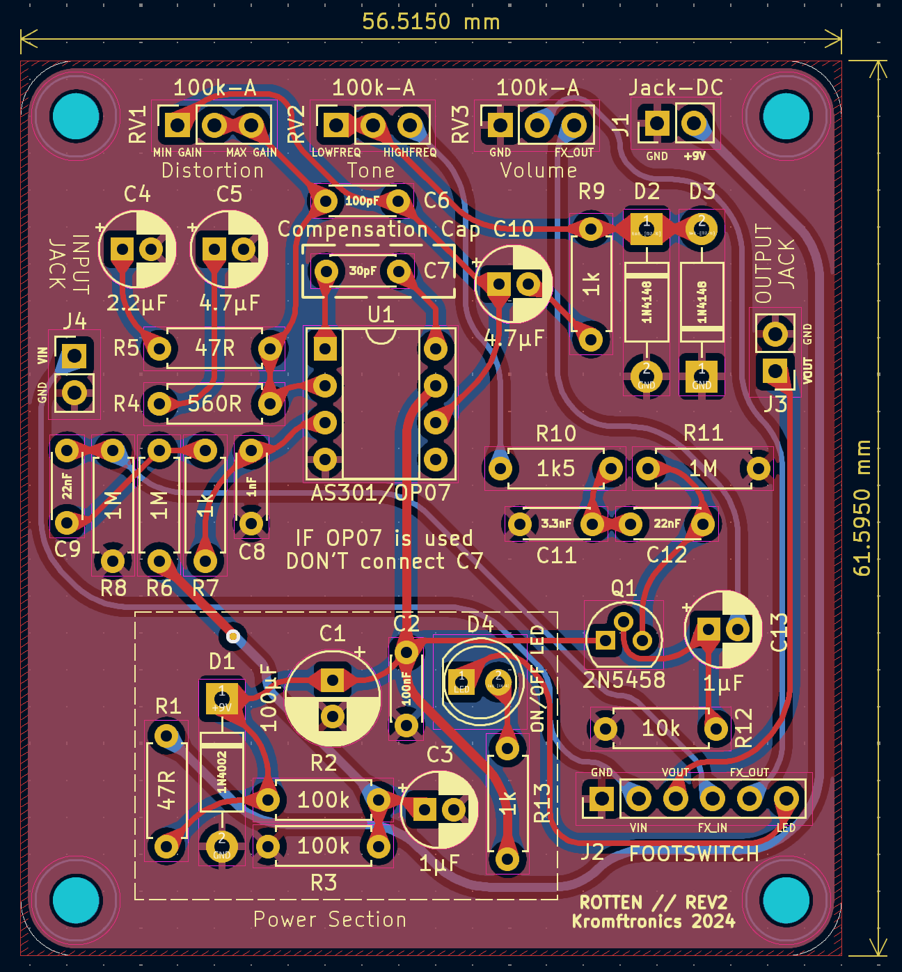
Rotten is an open-source printed circuit board by KamikazeVildsvin, from the KamikazeVildsvin/Rotten repository on GitHub, published under the GPL-3.0 licence. It is a 2-layer board of 56.5 × 61.6 mm with 43 parts on 26 nets, routed with 917 tracks and 1 via.
Its parts include 13 capacitors, 13 resistors, 4 diodes, 4 connectors and 1 IC.
This repository contains the KiCad files for a DIY clone of the classic Pro Co RAT distortion effect pedal. The schematic is an implementation of the one found on ElectroSmash, so a big shout-out to them. The article on ElectroSmash has a great description of the functionality of the circuit.
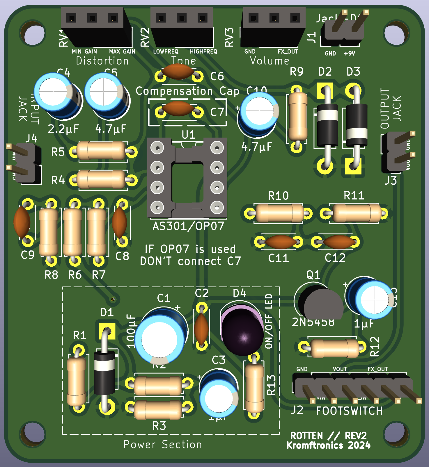
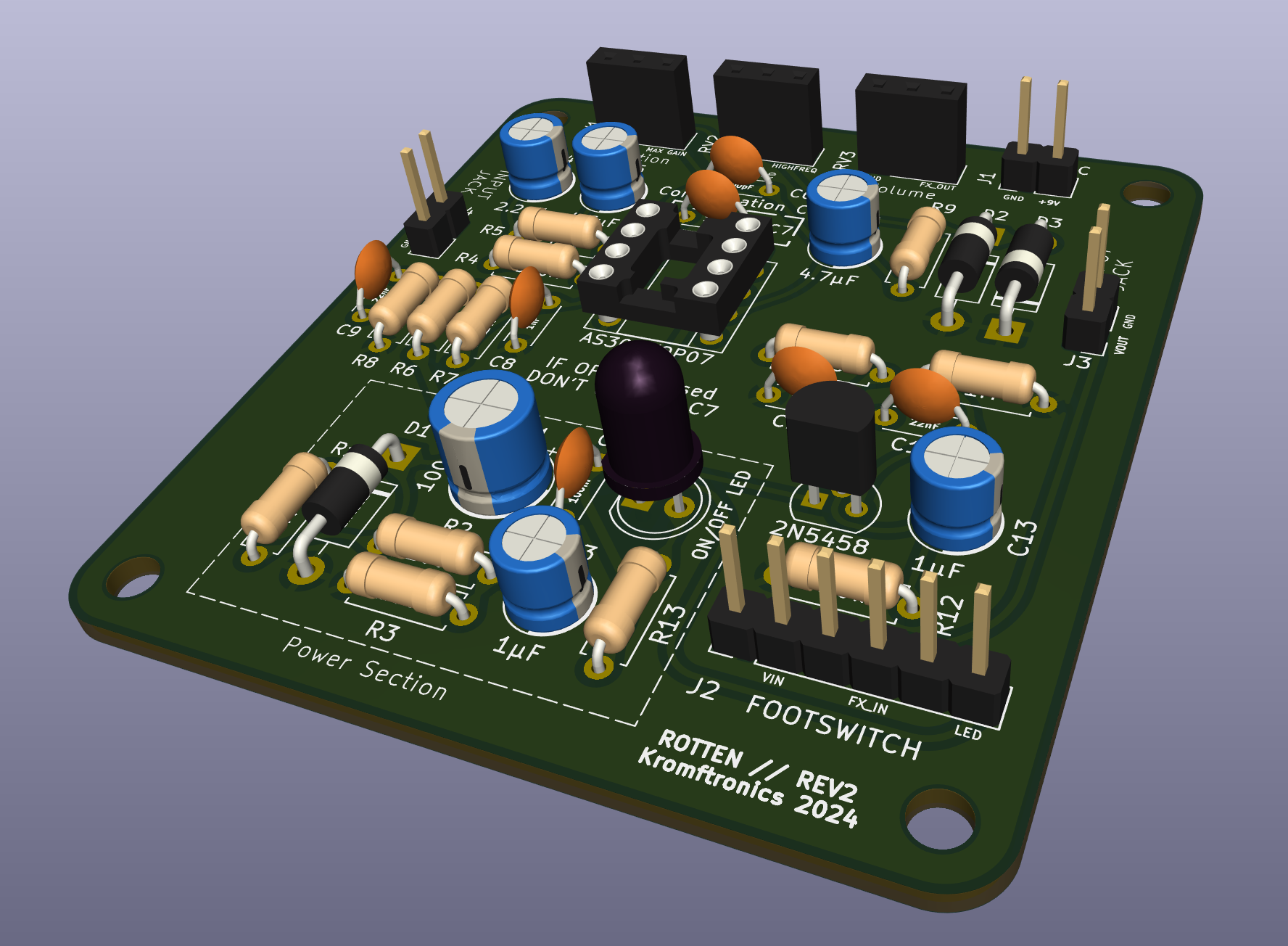
An interactive HTML BOM can be found in the PCB/Rotten/bom directory.
This can be used as a tool to easier populate the PCB.
You will need a 3PDT type switch in order to wire things correctly. The six connections on the PCB needs to be wired to the switch as indicated by the image below.
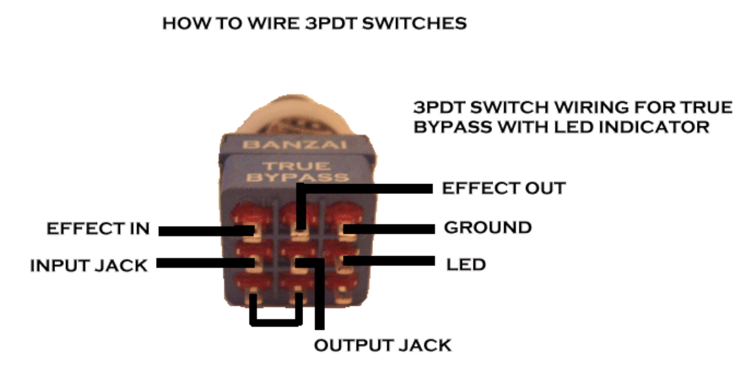 source: https://support.banzaimusic.com/article/53-true-bypass-switch-wiring
I would recommend that you use the interactive BOM above to see what connection on the PCB matches the correct pin on the footswitch, since the silkscreen is very small and probably not readable on the actual physical PCB.
NOTE: If you don't want to use the LED indicator, you can disregard the GROUND and LED connections on the footswitch and don't solder these connections to the PCB.
The PCB has been designed so pin 1, 2, and 3 on the board matches the pinout of the 100k Potentiometers. This means that pin 1 on the potentiometer should go to the square pad on the PCB, as indicated below.
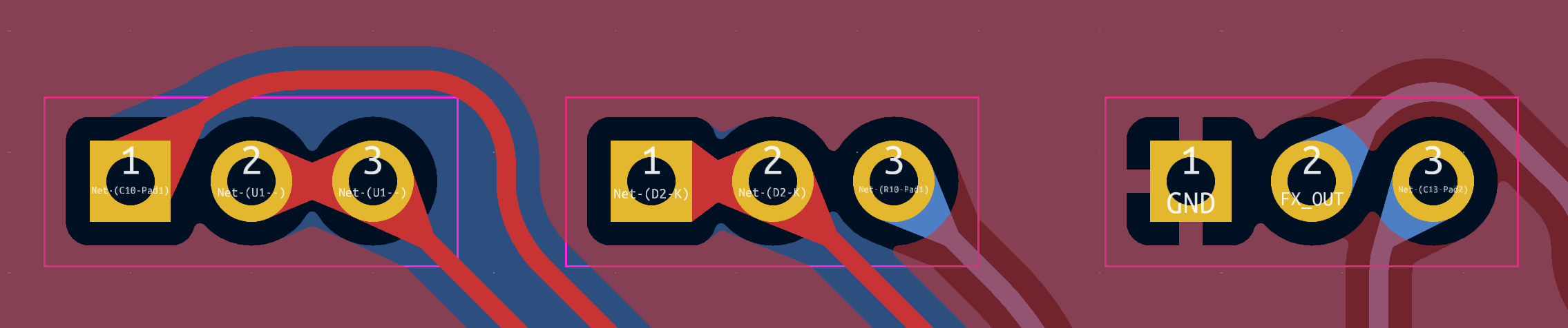
The Jack connectors (both the 1/4" audio jacks and the DC jack) only needs two connections. For the audio jacks, pin 1 should be soldered to the tib of the connector and the sleeve to pin 2. The silkscreen on the PCB also indicates which pad is ground or the signal, as can be seen below
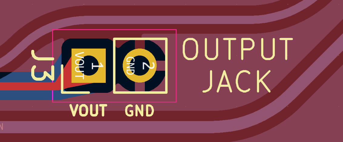
The DC barrek jack needs to be connected center negatic in order for the effect to work with standard stompbox power supplies. This means that you should connect the tip to ground and the +9V to the sleeve of the barrel jack connector.
| Qty | Value | Footprint | References |
|---|---|---|---|
| 4 | MountingHole | MountingHole:MountingHole_3.2mm_M3_DIN965 | H1, H2, H3, H4 |
| 3 | 100k-A | Connector_PinSocket_2.54mm:PinSocket_1x03_P2.54mm_Vertical | RV1, RV2, RV3 |
| 3 | 1M | Resistor_THT:R_Axial_DIN0207_L6.3mm_D2.5mm_P7.62mm_Horizontal | R6, R8, R11 |
| 3 | 1k | Resistor_THT:R_Axial_DIN0207_L6.3mm_D2.5mm_P7.62mm_Horizontal | R7, R9, R13 |
| 2 | 100k | Resistor_THT:R_Axial_DIN0207_L6.3mm_D2.5mm_P7.62mm_Horizontal | R2, R3 |
| 2 | 1N4148 | Diode_THT:D_DO-41_SOD81_P10.16mm_Horizontal | D2, D3 |
| 2 | 1µF | Capacitor_THT:CP_Radial_D5.0mm_P2.00mm | C3, C13 |
| 2 | 22nF | Capacitor_THT:C_Disc_D4.3mm_W1.9mm_P5.00mm | C9, C12 |
| 2 | 4.7µF | Capacitor_THT:CP_Radial_D5.0mm_P2.00mm | C5, C10 |
| 2 | 47R | Resistor_THT:R_Axial_DIN0207_L6.3mm_D2.5mm_P7.62mm_Horizontal | R1, R5 |
| 1 | 100nF | Capacitor_THT:C_Disc_D4.3mm_W1.9mm_P5.00mm | C2 |
| 1 | 100pF | Capacitor_THT:C_Disc_D4.3mm_W1.9mm_P5.00mm | C6 |
| 1 | 100µF | Capacitor_THT:CP_Radial_D6.3mm_P2.50mm | C1 |
| 1 | 10k | Resistor_THT:R_Axial_DIN0207_L6.3mm_D2.5mm_P7.62mm_Horizontal | R12 |
| 1 | 1N4002 | Diode_THT:D_DO-41_SOD81_P10.16mm_Horizontal | D1 |
| 1 | 1k5 | Resistor_THT:R_Axial_DIN0207_L6.3mm_D2.5mm_P7.62mm_Horizontal | R10 |
| 1 | 1nF | Capacitor_THT:C_Disc_D4.3mm_W1.9mm_P5.00mm | C8 |
| 1 | 2.2µF | Capacitor_THT:CP_Radial_D5.0mm_P2.00mm | C4 |
| 1 | 2N5458 | Package_TO_SOT_THT:TO-92 | Q1 |
| 1 | 3.3nF | Capacitor_THT:C_Disc_D4.3mm_W1.9mm_P5.00mm | C11 |
| 1 | 30pF | Capacitor_THT:C_Disc_D4.3mm_W1.9mm_P5.00mm | C7 |
| 1 | 560R | Resistor_THT:R_Axial_DIN0207_L6.3mm_D2.5mm_P7.62mm_Horizontal | R4 |
| 1 | AS301/OP07 | Package_DIP:DIP-8_W7.62mm_Socket | U1 |
| 1 | FOOTSWITCH | Connector_PinHeader_2.54mm:PinHeader_1x06_P2.54mm_Vertical | J2 |
| 1 | JACK INPUT | Connector_PinHeader_2.54mm:PinHeader_1x02_P2.54mm_Vertical | J4 |
| 1 | JACK OUTPUT | Connector_PinHeader_2.54mm:PinHeader_1x02_P2.54mm_Vertical | J3 |
| 1 | Jack-DC | Connector_PinHeader_2.54mm:PinHeader_1x02_P2.54mm_Vertical | J1 |
| 1 | ON/OFF LED | LED_THT:LED_D5.0mm_IRBlack | D4 |
google/mozc-devices
Circuit diagrams and firmware source code for Gboard DIY keyboards

rusefi/rusefi
rusefi - GPL internal combustion engine control unit


jrsteensen/OpenHornet
OpenHornet 1:1 F/A-18C Simulator Repository


tebl/RC6502-Apple-1-Replica
An expandable SBC-version of the Apple 1 computer, easy to get started with and lot of cool stuff that can be added to it!

nodestark/mdb-esp32-cashless
ESP32-based MDB cashless device for vending machines, supporting EVA DTS DEX/DDCMP telemetry and payments over the MDB protocol via Bluetooth and MQTT

zynthian/zynthian-hw
Zynthian hardware stuff: PCBs, schemes, parts specifications, pin assignment, ...
It measures 56.5 × 61.6 mm and has 2 copper layers, 1.6 mm thick.
43 parts. The full list of its parts is on this page, with links to each part's symbol and footprint where PCBKit's library has them.
From the KamikazeVildsvin/Rotten repository on GitHub, at the commit this page was made from: the board is PCB/Rotten/Rotten.kicad_pcb and its schematic PCB/Rotten/Rotten.kicad_sch. PCBKit opens the board in the browser, with nothing to install.
Its repository publishes it under the GPL-3.0 licence: you may reuse it on that licence's terms (keep the author's notice, and for a copyleft licence share your changes alike).