4 layers52 × 48 mm
Hand hub
6thSense-dev/mocap-glove
Magnetic MoCap glove firmware, tracking diagnostics and local hand visualizer
106 parts

 KabukiFlux/jammanator-pi4
JAMMANATOR the Raspberry Pi jamma board
Jamma raspi is an open-source printed circuit board by KabukiFlux, from the KabukiFlux/jammanator-pi repository on GitHub, published under the MIT licence. It is a 2-layer board of 132.5 × 105.7 mm with 149 parts on 197 nets, routed with 3,272 tracks and 236 vias.
It is built around the SN74LVC244APWRE4, 74HC86D and LM1117IMPX-3.3/NOPB-HXY, with the BAT54S among its other parts. Its parts include 32 diodes, 16 capacitors, 16 connectors and 9 ICs. It belongs with the retro computing and games and lEDs and displays boards of this library.


Jammanator, the Raspberry Pi JAMMA output board for your cabinet
This was done during some live events on Twitch.tv and tested for some time.
This is a very old design for Raspberry Pi 3B+, 4, 400, it no longer has the status that anybody can make money and make profit of it so I decided to publish it, if you have an arcade cabinet with JAMMA a spare Raspberry Pi 3B+ or 4 and you want to have something running then is a matter of burning the rgbpiOS or the recalboxOS and you have everything you need to make it work.
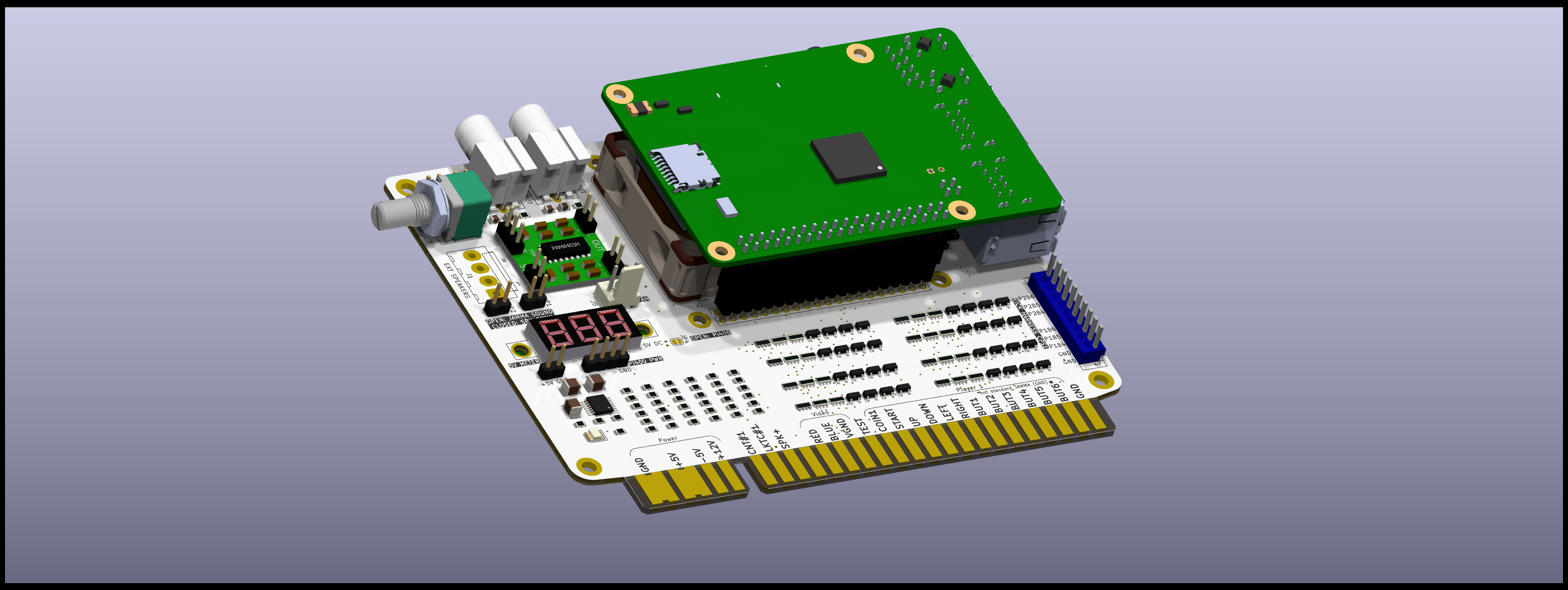
This board is intended to be a PCB used with a Raspberry Pi and a 4x4 5v fan to remove some heat from the CPU.
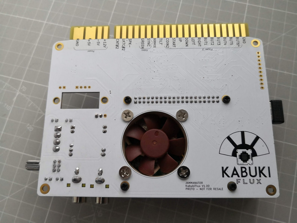
This board uses 2 I2C parallel expansion I/O chips connected to the JAMMA connector in order to map automatically the buttons to the cabinet with no configuration required.
A voltmeter has been added to check the 5v rail while running.
A protection circuit has been mapped to all the inputs and an extra buffer to avoid any loss of the I2C bus, if the I2C bus is lost the Raspberry will no longer boot the OS (yellow led) this design will avoid that.
In the BOM directory there's an interactive BOM with all the required components.
In the gerbers directory we have the gerbers to manufacture the boards.
In the KiCAD folder we can find the KiCAD project itself.
In the circuit_js folder you can find the simulation for the I/O protection.
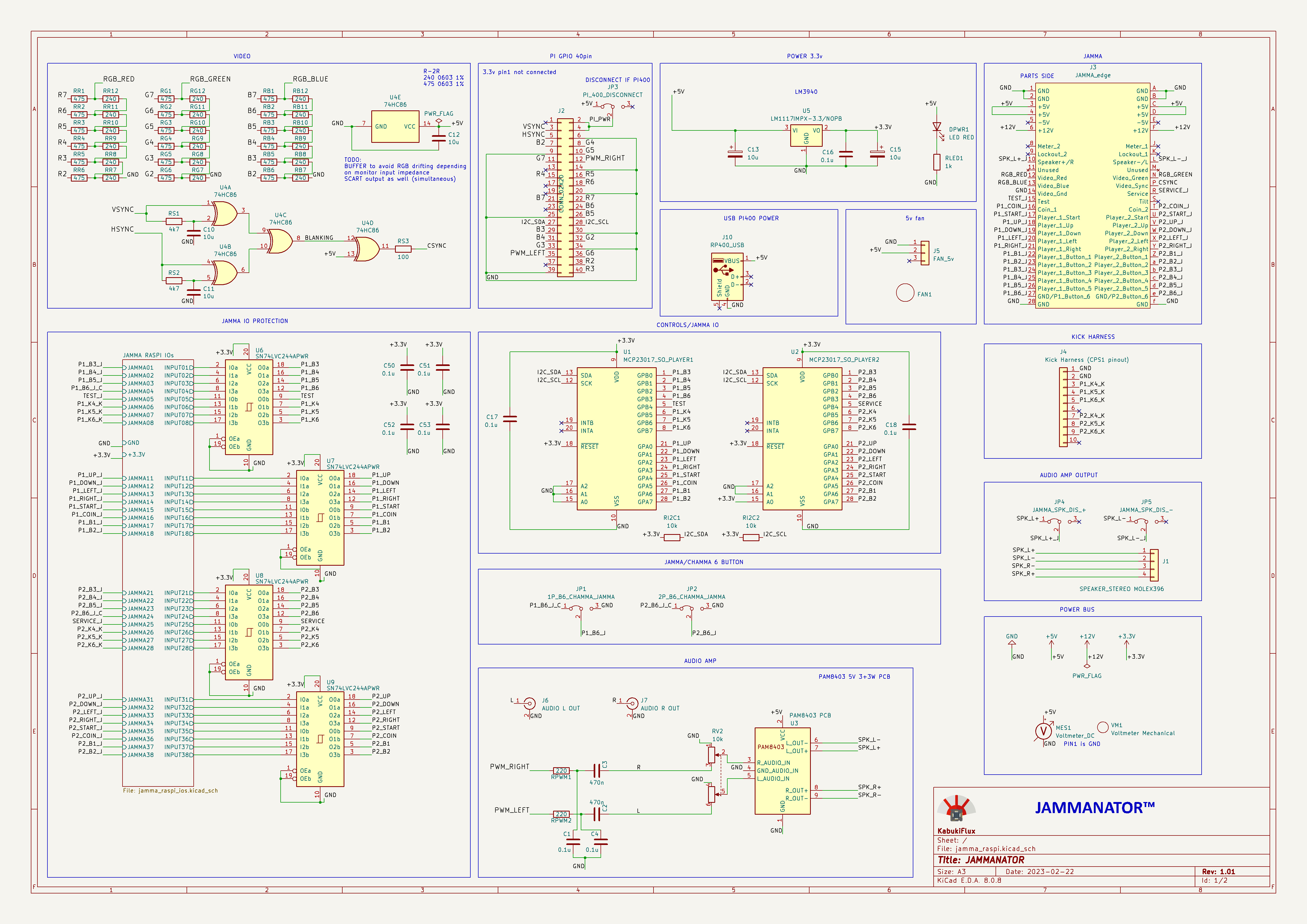
This is the schematics.
If you use a Raspberry Pi 400 (the one with the keyboard) I recommend this board and the extender in order to use it (check carefully the connector position):
Ensure the RP400 pin is in the right position, as the RP400 cannot be powered via the GPIO we must provide USB-C power and avoid sending power to the GPIO.
1- Send to manufacture the GERBER board to JLCPCB or other PCB manufacturer.
2- Get the components required, you can see here the Bill Of Materials BOM
3- Solder the components.
4- Connect a Raspberry Pi with rgbpi-OS or recalbox-OS
5- Follow the installation guide and instructions for the selected OS.
Once finished you should have something like this:
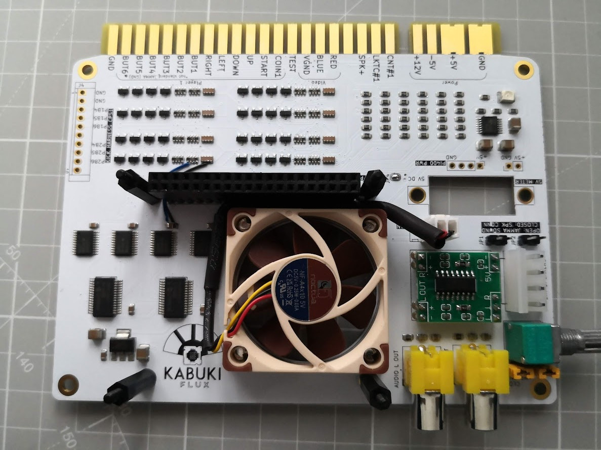
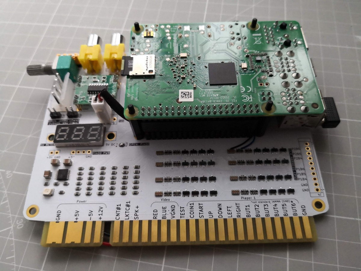
And yes, read below, no liability is assumed for misuse.
See LICENSE fo more information.
| Qty | Value | Footprint | References |
|---|---|---|---|
| 32 | BAT54S | Package_TO_SOT_SMD:SOT-23 | D1, D2, D10, D11, D12, D13, D14, D15, D16, D17, D18, D19, D20, D21, D22, D23 +16 |
| 18 | 240 | Resistor_SMD:R_0805_2012Metric | RB7, RB8, RB9, RB10, RB11, RB12, RG7, RG8, RG9, RG10, RG11, RG12, RR7, RR10, RR11, RR12 +2 |
| 18 | 475 | Resistor_SMD:R_0805_2012Metric | RB1, RB2, RB3, RB4, RB5, RB6, RG1, RG2, RG3, RG4, RG5, RG6, RR1, RR2, RR3, RR4 +2 |
| 9 | 0.1u | Capacitor_SMD:C_0805_2012Metric | C1, C4, C16, C17, C18, C50, C51, C52, C53 |
| 8 | 100n | jamma_raspi:C_Array_Convex_4x0612 | CN1, CN2, CN3, CN4, CN5, CN6, CN7, CN8 |
| 8 | 10k | Resistor_SMD:R_Array_Concave_4x0603 | RN2, RN4, RN6, RN8, RN10, RN12, RN14, RN16 |
| 8 | 1k | Resistor_SMD:R_Array_Concave_4x0603 | RN1, RN3, RN5, RN7, RN9, RN11, RN13, RN15 |
| 5 | 10u | Capacitor_SMD:C_1210_3225Metric_Pad1.33x2.70mm_HandSolder | C10, C11, C12, C13, C15 |
| 4 | MountingHole_3.2mm_M3_DIN965_Pad_TopBottom | MountingHole:MountingHole_3.2mm_M3_DIN965_Pad_TopBottom | M1, M2, M3, M4 |
| 4 | SN74LVC244APWR | Package_SO:TSSOP-20_4.4x6.5mm_P0.65mm | U6, U7, U8, U9 |
| 2 | 10k | Resistor_SMD:R_0805_2012Metric | RI2C1, RI2C2 |
| 2 | 220 | Resistor_SMD:R_0805_2012Metric | RPWM1, RPWM2 |
| 2 | 470n | Capacitor_SMD:C_0805_2012Metric | C2, C3 |
| 2 | 4k7 | Resistor_SMD:R_0805_2012Metric | RS1, RS2 |
| 1 | 100 | Resistor_SMD:R_0805_2012Metric | RS3 |
| 1 | 10k | jamma_raspi:Potentiometer_Alps_RK097_Dual_Horizontal | RV2 |
| 1 | 1P_B6_CHAMMA_JAMMA | Connector_PinHeader_2.54mm:PinHeader_1x03_P2.54mm_Vertical | JP1 |
| 1 | 1k | Resistor_SMD:R_0805_2012Metric | RLED1 |
| 1 | 2P_B6_CHAMMA_JAMMA | Connector_PinHeader_2.54mm:PinHeader_1x03_P2.54mm_Vertical | JP2 |
| 1 | 74HC86 | Package_SO:TSSOP-14_4.4x5mm_P0.65mm | U4 |
| 1 | AUDIO L OUT | kabuki:CUI_RCJ-043 | J6 |
| 1 | AUDIO R OUT | kabuki:CUI_RCJ-043 | J7 |
| 1 | CONN_02X20 | GPIO_raspi:GPIO_2x20_P2.54mm_Vertical_Tall_w_Standoffs | J2 |
| 1 | FAN_5v | Connector_Molex:Molex_KK-254_AE-6410-03A_1x03_P2.54mm_Vertical | J5 |
| 1 | JAMMA_SPK_DIS_+ | Connector_PinHeader_2.54mm:PinHeader_1x03_P2.54mm_Vertical | JP4 |
| 1 | JAMMA_SPK_DIS_- | Connector_PinHeader_2.54mm:PinHeader_1x03_P2.54mm_Vertical | JP5 |
| 1 | JAMMA_edge | jamma:JAMMA_edge | J3 |
| 1 | Kick Harness (CPS1 pinout) | JST_NH:B10P-SHF-1AA | J4 |
| 1 | LED RED | LED_SMD:LED_1210_3225Metric_Pad1.42x2.65mm_HandSolder | DPWR1 |
| 1 | LM1117IMPX-3.3/NOPB | Package_TO_SOT_SMD:SOT-223-3_TabPin2 | U5 |
| 1 | LOGO | kabuki:LogoKabuki | G2 |
| 1 | LOGO | kabuki:LogoKabuki_18mm | G1 |
| 1 | MCP23017_SO_PLAYER1 | Package_SO:SSOP-28_5.3x10.2mm_P0.65mm | U1 |
| 1 | MCP23017_SO_PLAYER2 | Package_SO:SSOP-28_5.3x10.2mm_P0.65mm | U2 |
| 1 | PAM8403 PCB | jamma_raspi:PAM8403_module | U3 |
| 1 | PI_400_DISCONNECT | Connector_PinHeader_2.54mm:PinHeader_1x03_P2.54mm_Vertical | JP3 |
| 1 | RP400_USB | Connector_USB:USB_A_Molex_67643_Horizontal | J10 |
| 1 | SPEAKER_STEREO MOLEX396 | Connector_Molex:Molex_KK-396_A-41791-0004_1x04_P3.96mm_Vertical | J1 |
| 1 | Voltmeter Mechanical | voltmeter:voltmeter | VM1 |
| 1 | Voltmeter_DC | Connector_PinHeader_2.54mm:PinHeader_1x02_P2.54mm_Vertical | MES1 |
| 1 | ~ | NOCTUA:Noctua_NF-A4x10_40mm | FAN1 |
6thSense-dev/mocap-glove
Magnetic MoCap glove firmware, tracking diagnostics and local hand visualizer

Bruhdows/klink
Klink is a magnetic tile system for building programmable machines. First up: a marble run with sensors, buttons, lights, gates, splitters and an elevator.

techmannih/pd1180-epr
PD1180-EPR — NEMA 34 Smart Motor-Mounted Stepper Controller with USB-C PD 3.1 EPR

DD1SB/ARDF-TX
Date: 2026-10-15. Engineering review only; unbuilt and unenergized. Open RF80.kicadpro, schematic and native PCB in KiCad10.0.6. Three primary PCBs and the separate VHF true-AM design are unchanged.

DeadlySIn777/Controller
Unfinished CNC controller motherboard: native KiCad sources, rules, DSN and global routing review


ItzJannis/CoRoSoN-Package_Draft
Draft version to the official CoRoSoN-Kit.
It measures 132.5 × 105.7 mm and has 2 copper layers, 1.6 mm thick.
149 parts, built around the SN74LVC244APWRE4, 74HC86D, LM1117IMPX-3.3/NOPB-HXY and BAT54S. The full list of its parts is on this page, with links to each part's symbol and footprint where PCBKit's library has them.
From the KabukiFlux/jammanator-pi repository on GitHub, at the commit this page was made from: the board is kicad/jamma_raspi.kicad_pcb and its schematic kicad/jamma_raspi.kicad_sch. PCBKit opens the board in the browser, with nothing to install.
Its repository publishes it under the MIT licence: you may reuse it on that licence's terms (keep the author's notice, and for a copyleft licence share your changes alike).