
2 layers100 × 82.8 mm
V1-cut10x10
KCORES/OCP2PCIe
OCP Mezzanine card V2.0 to standard PCIe slot adapter design
15 parts363GPL-3.0
 KCORES/OCP2PCIe363
OCP Mezzanine card V2.0 to standard PCIe slot adapter design
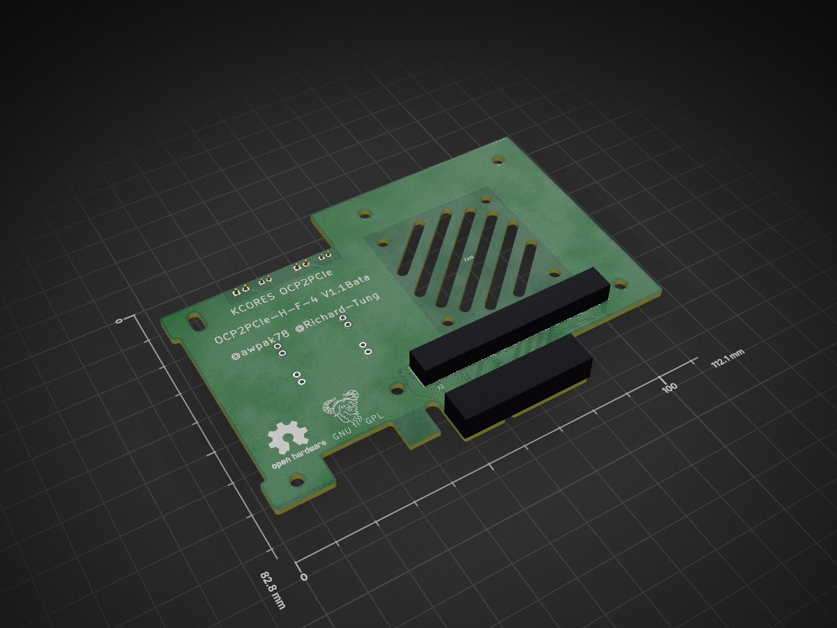
OCP2PCIe H F-4-V1.1Beta is an open-source printed circuit board by KCORES, from the KCORES/OCP2PCIe repository on GitHub, published under the GPL-3.0 licence. It is a 2-layer board of 112.1 × 82.8 mm with 15 parts on 70 nets, routed with 349 tracks and 97 vias.
It is built around the DM02. Its parts include 6 connectors, 4 capacitors and 1 IC. It belongs with the computers and single-board computers boards of this library.
修正鬼畜布线
覆铜
优化螺丝孔
刷新了版本号
添加切成10x10以内的版本
| Qty | Value | Footprint | References |
|---|---|---|---|
| 2 | C | Capacitor_SMD:C_1206_3216Metric | C3, C4 |
| 2 | Conn_01x02 | Connector_PinHeader_2.00mm:PinHeader_1x02_P2.00mm_Vertical | J4, J6 |
| 2 | Conn_01x02 | Connector_PinHeader_2.54mm:PinHeader_1x02_P2.54mm_Vertical | J3, J5 |
| 1 | C | Capacitor_SMD:CP_Elec_6.3x5.4 | C1 |
| 1 | C | Capacitor_Tantalum_SMD:CP_EIA-7343-31_Kemet-D | C2 |
| 1 | Conn_02x40_Top_Bottom | FCI_61082:FCI_61082_12xxxxLF | J2 |
| 1 | DM02 | FCI_61082:DM02 | U1 |
| 1 | Fan_4010 | FCI_61082:Fan_4010 | FAN |
| 1 | PCI Express x4 | Connector_PCBEdge:BUS_PCIexpress_x4 | J1 |
| 1 | TestPoint_2Pole | FCI_61082:TestPlot | TP1 |
The 13 most common of 15 parts.
KCORES/OCP2PCIe
OCP Mezzanine card V2.0 to standard PCIe slot adapter design


google/mozc-devices
Circuit diagrams and firmware source code for Gboard DIY keyboards

hoglet67/RGBtoHDMI
Bare-metal Raspberry Pi project that provides pixel-perfect sampling of Retro Computer RGB/YUV video and conversion to HDMI

mntmn/amiga2000-gfxcard
MNT VA2000, an Open Source Amiga 2/3/4000 Graphics Card (Zorro II/III), written in Verilog

hackclub/OnBoard
💡 Join 1,000 teenagers and make your first PCB with a $100 grant!

kenp-io/not-for-airpods-repairs
The content of this repository is licensed under the WTFPL License. Please have a close look at the terms before using this material.

Luos-io/luos_engine
Open-source and real-time orchestrator for cyber-physical-systems, to easily design, test and deploy embedded applications and digital twins.

Chrismettal/EleLab_v2
Cheap DIY lab system for hobbyists and the tinkering folk
It measures 112.1 × 82.8 mm and has 2 copper layers, 1.6 mm thick.
15 parts, built around the DM02. The full list of its parts is on this page, with links to each part's symbol and footprint where PCBKit's library has them.
From the KCORES/OCP2PCIe repository on GitHub, at the commit this page was made from: the board is OCP2PCIe-H-F-4/OCP2PCIe-H-F-4-V1.1Beta/V1.kicad_pcb. PCBKit opens the board in the browser, with nothing to install.
Its repository publishes it under the GPL-3.0 licence: you may reuse it on that licence's terms (keep the author's notice, and for a copyleft licence share your changes alike).