2 layers43.6 × 55.1 mm

 JustCuzRobotics/Just_Cuz_Logging_Current_Meter
A 150 A / 60 V inline power meter and datalogger for RC ESC test benches, a WM150-class meter with live logging, a graphing touchscreen, and thermistor plus ESC-signal channels.
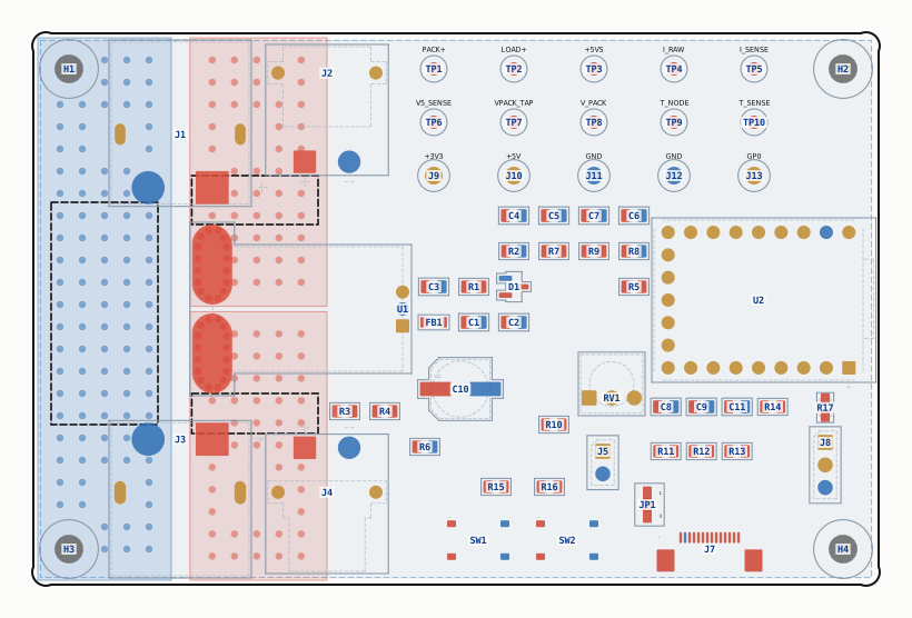
Logging Current Meter is an open-source printed circuit board by JustCuzRobotics, from the JustCuzRobotics/Just_Cuz_Logging_Current_Meter repository on GitHub. It is a 4-layer board of 95 × 62 mm with 62 parts on 38 nets, routed with 327 tracks and 255 vias.
It is built around the ACS770KCB-150U-PFF-T, RP2040-ZERO and BAT54S, with the XT30PW-M, XT30PW-F and XT60PW-F among its other parts. Its parts include 17 resistors, 12 connectors, 11 capacitors, 2 ICs and 2 switches. It belongs with the sensors and measurement boards and the RP2040 boards of this library.


A 150 A / 60 V inline power meter and datalogger for RC ESC test benches, a WM150-class meter with live logging, a graphing touchscreen, and thermistor plus ESC-signal channels.
Status: Rev A built, assembled and brought up (2026-08-25). Display, capacitive touch,
all four analog channels, backlight and the ESC output all work. Voltage and thermistor are
calibrated. Two known Rev A faults: the buttons are dead (footprint pad mapping) and
JP1 ships open. See "Known open items". Bring-up firmware is in firmware/.
| Parameter | Value |
|---|---|
| Max voltage | 60 V DC (14S LiPo) |
| Max current | 150 A burst, ~60 A continuous, limited by the XT60 rather than the sensor |
| Current sensor | ACS770KCB-150U, Hall, galvanically isolated, 100 µΩ conductor |
| MCU | Waveshare RP2040-Zero |
| Display | 3.5" 480×320 IPS, ST7796U + FT6336U touch + microSD, 14-way FPC |
| Logging | microSD and USB CDC CSV, up to 76 Hz (every sample tick) |
| Channels | current, pack voltage, 5 V rail, 1× 100 k NTC, plus ESC signal out |
| Board | 95 × 62 mm, 4 layer, 1 oz outer / 0.5 oz inner |
| Assembled PCB | ≈ $15/board delivered, at qty 10 (JLCPCB: bare board + SMT parts + assembly + shipping) |
| Complete unit | ≈ $44/board, adding the display, RP2040-Zero, connectors, NTC and hardware |
Read the accuracy budget in DESIGN.md §5 before trusting a number. Short
version: honest between roughly 30 A and 150 A, and increasingly meaningless below ~20 A,
because a ±1%-of-full-scale nonlinearity term is a fixed ±1.5 A regardless of reading. That
is inherent to putting a 150 A Hall sensor on a small current. For comparative testing,
same board, same session, ESC A vs ESC B, the systematic terms cancel and repeatability is
far better than the absolute figures.
The ratiometric trick (§4.2). The sensor's output scales with its own supply, which here is raw USB VBUS, sagging with cable resistance and modulated by the display backlight PWM. Rather than fight that with a regulator, a second divider measures the 5 V rail, and the current is recovered from the ratio. Both V_CC and V_REF cancel algebraically, so accuracy depends only on two resistor ratios and the sensor's own spec.
The current path crosses the short dimension. The ACS770's terminals sit side by side, so rotating it 90° and stacking the connectors above and below gives a ~28 mm connector-to- connector path. The ground return, not the sensor, turns out to dominate the loss budget. See §8.
Logging_Current_Meter.kicad_sch    schematic
Logging_Current_Meter.kicad_pcb    board, 95 × 62 mm, 4 layer
LCM.kicad_sym / LCM.pretty         all project symbols and footprints, self-contained
production/                        gerbers, BOM, positions and IPC netlist as sent to fab
DESIGN.md                          the real documentation, reasoning, maths, decisions
BOM.md / BOM.csv                   bill of materials, generated from the schematic
generator/                         the Python that builds and checks all of the above
firmware/                          bring-up diagnostic and the touchscreen UI, one folder per sketch
tools/capture_stream.py            records the meter's USB CSV stream on a PC
tools/log_analyzer.py              GUI: graphs, summary CSV and run comparisons from SD logs
libraries/JCR_TouchScreen/         reusable ST7796 + FT6336U display and touch library
COMMIT_TIMELINE.md                 full detail behind every commit, newest first
DESIGN.md is the substantive document; this README is only an index. It records why
each choice was made, including the ones that turned out wrong and were reversed.
The schematic and board are hand-edited in KiCad, but every mechanical change is applied by script and checked by an independent verifier. The rule throughout: the checker re-reads the finished file from disk and re-derives everything, so it can disagree with the tool that wrote it.
Requires KiCad 10 or newer. The schematic and board are now in KiCad 10 format
(20260306 and 20260206), written by KiCad itself. KiCad refuses to open files stamped
newer than the running version, so an older install will not open this project at all.
cd generator

# check, read-only, safe at any time
python3 verify.py     ../Logging_Current_Meter.kicad_sch ../LCM.kicad_sym
python3 verify_pcb.py ../Logging_Current_Meter.kicad_pcb ../Logging_Current_Meter.kicad_sch

# regenerate derived artefacts
python3 gen_bom.py                                    # BOM.md + BOM.csv from the schematic
python3 copper_budget.py ../Logging_Current_Meter.kicad_pcb   # 150 A loss budget
python3 region_map.py    ../Logging_Current_Meter.kicad_pcb   # the §14 layout map
python3 render_pcb.py    ../Logging_Current_Meter.kicad_pcb ../placement.svg
gen_sch.pyis a historical build script, not a live tool.generator/kicad8.pyhardcodesSCH_VERSION = 20231120, so re-running it would overwrite the KiCad 10 schematic with a KiCad 8 one and discard every edit made in KiCad since.gen_pcb.pywas updated for KiCad 10;gen_sch.pywas not.
verify.py rebuilds the netlist geometrically, so pins, wire endpoints and label anchors
sharing a coordinate are one node, then compares it against an independently written
expectation of all nets and pin connections. verify_pcb.py runs nine checks over the
board: s-expression syntax, footprint inventory against the schematic, net coverage, board
extent, courtyard overlaps, stale net names, pour and stitching integrity, components inside
soldermask openings, and pad-to-pad clearance against the resolved netclass rules.
Both currently pass clean.
gen_pcb.pywill refuse to run itsplaceorpourstages once the board has routed tracks, because both would destroy hand routing. Override with--forceonly after re-syncing the placement table from the board.
Every check in verify_pcb.py exists because something actually went wrong: a quoted
s-expression tag that made KiCad reject the file, a net rename that left a dead name on a
live pad, a resistor placed inside a soldermask aperture, a netclass clearance that made a
0.5 mm-pitch connector unroutable. The commentary in the source explains each one.
JP1 ships open — bridge it or the display is dead. It is the display's only supply.
Bridge pad 2 (DISP_VCC) to pad 1 (+5V). No backlight, no SPI and no I²C until you do,
which makes it look like a much bigger problem than it is. DESIGN.md §9.J7 needs a TYPE A (same-side) FFC cable. The one in the display's box is Type B and
reverses the pin order, putting 5 V on the module's SD_CS while VCC sits unpowered.
14 pin, 0.5 mm pitch, Type A, ≤100 mm. DESIGN.md §9.SW_TS-1187A was remapped
assuming internal pairs 1–3/2–4; they are 1–2/3–4, so both buttons short BTN1 to GND
permanently. Rev B fix, plus a lift-two-legs bodge for Rev A. Calibration runs from
serial commands instead. DESIGN.md §9.T_NODE and T_POT_TOP re-routed. DESIGN.md §4.4.firmware/display_bringup/. It exercises
all 20 GPIO, reports pass/fail per subsystem with net names, and runs the calibration
routines.firmware/logging_current_meter_FABLE/
(v3.6): live V/I/T/W, energy accumulation, an autoscaled 5 s graph, Test Mode (ESC
signal on GP1 for uni- or bidirectional ESCs — manual buttons or slider with a dead-man
option, ramped auto-cycle, and a counted Log Test that records itself), SD logging
(manual, Test-cycle or current-threshold start, 1–15 min duration) with a USB CSV
stream, a Settings screen
with flash persistence and a settable wall clock that stamps every log with the date and
time it was recorded, dark and navy themes, a tunable weighted filter on the V and I
readings, and a touch diagnostic screen with a serial telemetry harness. Its display and
touch stack is factored out into libraries/JCR_TouchScreen/. Architecture and the
measured sampling constraints are in DESIGN.md §11.0xFF is the expected reading. The §11 question only has meaning with
a card inserted.Three cost figures get confused, so to be explicit. BOM.md's $10.75 is the theoretical
SMT parts cost at LCSC unit prices, and it is the only one the generator computes. The
$15 above is what a delivered assembled board actually cost at qty 10, and the real
PCBA line came in at $11.06/board against that $10.75 estimate, which is close enough to
validate the generated BOM. $44 is a complete working meter, and the display alone is
$18.99 of it. All three are at qty 10; setup and shipping amortise, so a one-off build costs
considerably more per board.
The ACS770 is marked not for new designs but remains in stock. ACS772KCB-150U-PFF-T is
a drop-in replacement requiring no board changes at all, same package, same 26.66 mV/A,
same quiescent output, same ratiometric behaviour, same load limits. DESIGN.md §4.1.1 has
the full comparison, including which of the commonly-quoted differences are wrong.
generator/):
PolyForm Noncommercial 1.0.0, plus the same additional permissions.Build one. Build several. Modify the design. Use it at work, in a business, in a makerspace, in a classroom, or in a paid repair shop. Put it in a monetised YouTube video, a paid course, or a magazine article. Publish your modified version, as long as you credit this project and licence your version the same way.
Sell the design files. Sell hardware built from them, whether assembled boards, bare PCBs, or kits. Bundle either into a product you sell. Selling kits is how this project funds itself, so that part is reserved.
Want to sell something based on this? Ask. Contact team@justcuzrobotics.com.
CC BY-NC-SA's "NonCommercial" clause is broader than the intent above; read strictly it would also block using one at work or in a monetised video. The additional permissions in the LICENSE files grant those uses explicitly, so the only real restriction is on selling the design or hardware.
Because commercial sale is restricted, this is source-available rather than open source in the OSI or OSHWA sense.
Copyright © 2026 Seth Schaffer / Just 'Cuz Robotics
| Qty | Value | Footprint | References |
|---|---|---|---|
| 6 | 100n | Capacitor_SMD:C_0805_2012Metric | C1, C5, C6, C7, C9, C11 |
| 5 | 0R | Resistor_SMD:R_0805_2012Metric | R10, R11, R12, R13, R14 |
| 4 | M3 board | LCM:MountingHole_M3_3.2mm | H1, H2, H3, H4 |
| 3 | 10k 1% | Resistor_SMD:R_0805_2012Metric | R5, R6, R8 |
| 2 | 100k 1% | Resistor_SMD:R_0805_2012Metric | R3, R4 |
| 2 | 10k DNP | Resistor_SMD:R_0805_2012Metric | R15, R16 |
| 2 | 10n | Capacitor_SMD:C_0805_2012Metric | C3, C4 |
| 2 | 10u | Capacitor_SMD:C_0805_2012Metric | C2, C8 |
| 2 | 1k | Resistor_SMD:R_0805_2012Metric | R7, R9 |
| 2 | GND | LCM:RailPad_THT_D1.0mm | J11, J12 |
| 1 | +3V3 | LCM:RailPad_THT_D1.0mm | J9 |
| 1 | +5V | LCM:RailPad_THT_D1.0mm | J10 |
| 1 | +5VS | LCM:TestPoint_D1.5mm | TP3 |
| 1 | 100R | Resistor_SMD:R_0805_2012Metric | R17 |
| 1 | 100k | easyECADDownloader:RES-ADJ-TH_3362P | RV1 |
| 1 | 100u 16V | Capacitor_SMD:CP_Elec_6.3x5.4 | C10 |
| 1 | 2.4k 1% | Resistor_SMD:R_0805_2012Metric | R1 |
| 1 | 4.7k 1% | Resistor_SMD:R_0805_2012Metric | R2 |
| 1 | 5V / 3V3 | LCM:SolderJumper_3_P1.3mm_Open | JP1 |
| 1 | 600R@100MHz 2A | Inductor_SMD:L_0805_2012Metric | FB1 |
| 1 | ACS770KCB-150U-PFF-T | easyECADDownloader:SENSOR-TH_ACS758KCB-150B-PFF-T (1) | U1 |
| 1 | BAT54S | Package_TO_SOT_SMD:SOT-23 | D1 |
| 1 | Display 14p FPC 0.5mm | LCM:FPC_05F_14PH20_P0.5mm | J7 |
| 1 | ESC 3-pin | LCM:PinHeader_1x03_P2.54mm_Vertical | J8 |
| 1 | GP0 | LCM:RailPad_THT_D1.0mm | J13 |
| 1 | I_RAW | LCM:TestPoint_D1.5mm | TP4 |
| 1 | I_SENSE | LCM:TestPoint_D1.5mm | TP5 |
| 1 | LOAD+ | LCM:TestPoint_D1.5mm | TP2 |
| 1 | MODE | LCM:SW_TS-1187A_5.1x5.1mm | SW1 |
| 1 | NTC 100k B3950 | Connector_PinHeader_2.54mm:PinHeader_1x02_P2.54mm_Vertical | J5 |
| 1 | PACK+ | LCM:TestPoint_D1.5mm | TP1 |
| 1 | RP2040-Zero | LCM:RP2040_Zero_Castellated | U2 |
| 1 | T_NODE | LCM:TestPoint_D1.5mm | TP9 |
| 1 | T_SENSE | LCM:TestPoint_D1.5mm | TP10 |
| 1 | V5_SENSE | LCM:TestPoint_D1.5mm | TP6 |
| 1 | VPACK_TAP | LCM:TestPoint_D1.5mm | TP7 |
| 1 | V_PACK | LCM:TestPoint_D1.5mm | TP8 |
| 1 | XT30 | LCM:XT30PW-M | J2 |
| 1 | XT30 | LCM:XT30PW-F | J4 |
| 1 | XT60 | LCM:XT60PW-F | J3 |
| 1 | XT60 | LCM:XT60PW-M | J1 |
| 1 | ZERO/TARE | LCM:SW_TS-1187A_5.1x5.1mm | SW2 |

Arrow-air/project-quiver
Project Quiver documentation, designs, and project artifacts.


Stab-Rabbit-coding/Serenity-UAV
A functional, security conscious, Unmanned Aerial Vehicle based on the Firefly Class spacecraft Serenity from the 2002 show..


ErdemA33/stm32f405-flight-controller
Open-source ArduPilot-compatible flight controller for fixed-wing UAVs. STM32F405, 4-layer KiCad design, built in 5 modular stages.
It measures 95 × 62 mm and has 4 copper layers, 1.6 mm thick.
62 parts, built around the ACS770KCB-150U-PFF-T, RP2040-ZERO, BAT54S and XT30PW-M. The full list of its parts is on this page, with links to each part's symbol and footprint where PCBKit's library has them.
From the JustCuzRobotics/Just_Cuz_Logging_Current_Meter repository on GitHub, at the commit this page was made from: the board is Logging_Current_Meter.kicad_pcb and its schematic Logging_Current_Meter.kicad_sch. PCBKit opens the board in the browser, with nothing to install.
Its repository states no licence, so its author keeps all rights: ask JustCuzRobotics before reusing the design.