2 layers53 × 42 mm
Input
Joshua-Benfell/ECEN405_ClassDAmplifier
Further reading: on output filter types for class-d amplifiers and BTL configurations on Wikipedia
37 parts

 Joshua-Benfell/ECEN405_ClassDAmplifier
Further reading: on output filter types for class-d amplifiers and BTL configurations on Wikipedia
DClassAmplifier is an open-source printed circuit board by Joshua-Benfell, from the Joshua-Benfell/ECEN405_ClassDAmplifier repository on GitHub. It is a 2-layer board of 100 × 75 mm with 92 parts on 49 nets, routed with 262 tracks and 39 vias.
It is built around the AD8567ARUZ, MAX4016ESA+ and L78M10ABDT-TR. Its parts include 27 resistors, 20 capacitors, 6 ICs, 5 connectors and 4 transistors.


2V Peak to peak (+1V to -1V) with at least 1V input sensitivity.
Needs to filter frequencies above 200Hz, but not the 200Hz point such that it has equivalent gain.
Will likely need to be a Bridge Tied load (BTL) configuration, as BTL output filters do not require DC blocking caps, which limit the low frequency response of the amplifier, and can be quite large.
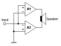
Further reading: on output filter types for class-d amplifiers and BTL configurations on Wikipedia
Cut-off point at 2kHz so that the cut-off is 1 decade above the 200Hz at the top of the bandwidth. This will avoid the phase change since it starts 1 decade before the cut-off. Make a Bode plot. No HPF for input as it is not needed.
Possible approaches:
To produce a clean triangle wave is complicated with a 555, simpler circuits with a 555 don't seem to guarantee a good output triangle wave. Furthermore, 55 timer circuits are more expensive and have a larger footprint.
A comparator integrator, is able to provide a reliably clean triangle wave and is fairly simple to implement.
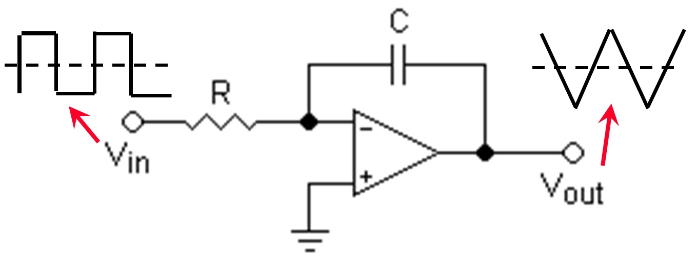
The frequency of the triangle wave will be above the audible range of frequencies at 22kHz.
The package used will be: MAX4016
Two key constraints with switching frequency:
| Qty | Value | Footprint | References |
|---|---|---|---|
| 12 | TestPoint | TestPoint:TestPoint_THTPad_D1.5mm_Drill0.7mm | TP1, TP2, TP3, TP4, TP5, TP6, TP7, TP8, TP9, TP10, TP11, TP12 |
| 5 | 10k | Resistor_SMD:R_0603_1608Metric_Pad0.98x0.95mm_HandSolder | R6, R9, R11, R26, R27 |
| 5 | 10u 50V | Capacitor_SMD:C_1206_3216Metric_Pad1.33x1.80mm_HandSolder | C1, C11, C12, C13, C14 |
| 4 | 10 | Resistor_SMD:R_2512_6332Metric_Pad1.40x3.35mm_HandSolder | R16, R18, R19, R21 |
| 4 | 100n | Capacitor_SMD:C_0603_1608Metric_Pad1.08x0.95mm_HandSolder | C4, C5, C15, C17 |
| 4 | 1Meg | Resistor_SMD:R_0603_1608Metric_Pad0.98x0.95mm_HandSolder | R1, R4, R14, R15 |
| 4 | 1k | Resistor_SMD:R_0603_1608Metric_Pad0.98x0.95mm_HandSolder | R2, R3, R12, R13 |
| 4 | Conn_01x02 | TerminalBlock:TerminalBlock_bornier-2_P5.08mm | J1, J3, J4, J5 |
| 4 | MountingHole | MountingHole:MountingHole_3.2mm_M3_ISO7380_Pad | H1, H2, H3, H4 |
| 4 | PHP23NQ11T,127 | Package_TO_SOT_THT:TO-220-3_Horizontal_TabDown | Q1, Q2, Q3, Q4 |
| 4 | SolderJumper_2_Open | Jumper:SolderJumper-2_P1.3mm_Open_RoundedPad1.0x1.5mm | JP1, JP2, JP3, JP4 |
| 2 | 12k | Resistor_SMD:R_0603_1608Metric_Pad0.98x0.95mm_HandSolder | R24, R25 |
| 2 | 2.8u | Capacitor_THT:CP_Radial_D8.0mm_P3.50mm | C19, C20 |
| 2 | 20k | Resistor_SMD:R_0603_1608Metric_Pad0.98x0.95mm_HandSolder | R17, R20 |
| 2 | 220u | HCTI-220-5.8:IND_HCTI-220-5.8 | L1, L2 |
| 2 | DGD05463FN-7 | DGD05463:SON50P300X300X80-11N-D | U3, U4 |
| 1 | 10m | Capacitor_THT:CP_Radial_D18.0mm_P7.50mm | C2 |
| 1 | 10n | Capacitor_SMD:C_0603_1608Metric_Pad1.08x0.95mm_HandSolder | C16 |
| 1 | 10u | Capacitor_SMD:C_0603_1608Metric_Pad1.08x0.95mm_HandSolder | C7 |
| 1 | 14u | OutputFilmCapacitor:C4AQLBU5140M18K | C18 |
| 1 | 16k | Resistor_SMD:R_0603_1608Metric_Pad0.98x0.95mm_HandSolder | R5 |
| 1 | 2.2k | Resistor_SMD:R_0603_1608Metric_Pad0.98x0.95mm_HandSolder | R22 |
| 1 | 22k | Resistor_SMD:R_0603_1608Metric_Pad0.98x0.95mm_HandSolder | R7 |
| 1 | 27k | Resistor_SMD:R_0603_1608Metric_Pad0.98x0.95mm_HandSolder | R23 |
| 1 | 330n | Capacitor_SMD:C_0603_1608Metric_Pad1.08x0.95mm_HandSolder | C3 |
| 1 | 4.7n | Capacitor_SMD:C_0603_1608Metric_Pad1.08x0.95mm_HandSolder | C8 |
| 1 | 47n | Capacitor_SMD:C_0603_1608Metric_Pad1.08x0.95mm_HandSolder | C6 |
| 1 | 5.6n | Capacitor_SMD:C_0603_1608Metric_Pad1.08x0.95mm_HandSolder | C10 |
| 1 | 56n | Capacitor_SMD:C_0603_1608Metric_Pad1.08x0.95mm_HandSolder | C9 |
| 1 | 620 | Resistor_SMD:R_0603_1608Metric_Pad0.98x0.95mm_HandSolder | R8 |
| 1 | 750 | Resistor_SMD:R_0603_1608Metric_Pad0.98x0.95mm_HandSolder | R10 |
| 1 | AD8567ARUZ | AD8567ARUZ:AD8567ARUZ | U2 |
| 1 | Conn_01x03 | TerminalBlock:TerminalBlock_bornier-3_P5.08mm | J2 |
| 1 | L78M10ABDT | Package_TO_SOT_SMD:TO-252-2 | U1 |
| 1 | LM319 | Package_SO:SO-14_3.9x8.65mm_P1.27mm | U6 |
| 1 | LOGO | Fry:Fry | G*** |
| 1 | MAX4016ESA+ | MAX4016ESA:MAX4016ESA&plus_ | U5 |
| 1 | Net-Tie_2 | NetTie:NetTie-2_SMD_Pad2.0mm | NT1 |
The 86 most common of 92 parts.
Joshua-Benfell/ECEN405_ClassDAmplifier
Further reading: on output filter types for class-d amplifiers and BTL configurations on Wikipedia

Joshua-Benfell/ECEN405_ClassDAmplifier
Further reading: on output filter types for class-d amplifiers and BTL configurations on Wikipedia

Joshua-Benfell/ECEN405_ClassDAmplifier
Further reading: on output filter types for class-d amplifiers and BTL configurations on Wikipedia


cardonabits/haxo-hw
Haxophone, an electronic musical instrument that resembles a saxophone

Allen-Synthesis/EuroPi
EuroPi: A reprogrammable Eurorack module based on the Raspberry Pi Pico

mmccoyd/hillside
Family of split ergonomic keyboards with three rows of six or five keys and a generous thumb arc

ChrisChrisLoLo/keezyboost40
4x10 ortholinear with an LCD in the middle. Uses the Raspberry Pi Pico, as well as Rust firmware

nodestark/mdb-esp32-cashless
ESP32-based MDB cashless device for vending machines, supporting EVA DTS DEX/DDCMP telemetry and payments over the MDB protocol via Bluetooth and MQTT
It measures 100 × 75 mm and has 2 copper layers, 1.6 mm thick.
92 parts, built around the AD8567ARUZ, MAX4016ESA+ and L78M10ABDT-TR. The full list of its parts is on this page, with links to each part's symbol and footprint where PCBKit's library has them.
From the Joshua-Benfell/ECEN405_ClassDAmplifier repository on GitHub, at the commit this page was made from: the board is Kicad/DClassAmplifier/DClassAmplifier.kicad_pcb. PCBKit opens the board in the browser, with nothing to install.
Its repository states no licence, so its author keeps all rights: ask Joshua-Benfell before reusing the design.