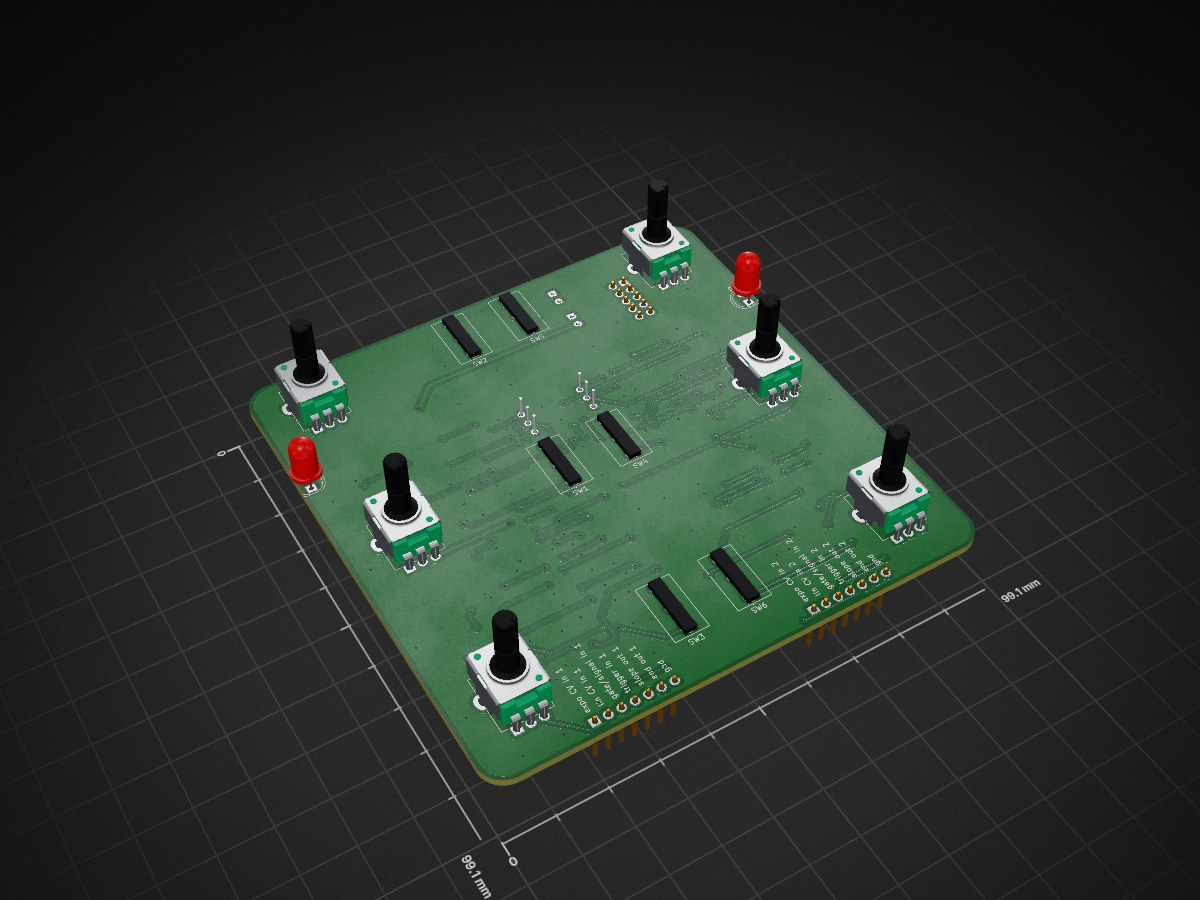
2 layers99.1 × 99.1 mm
 JordanAceto/angelo_modular2
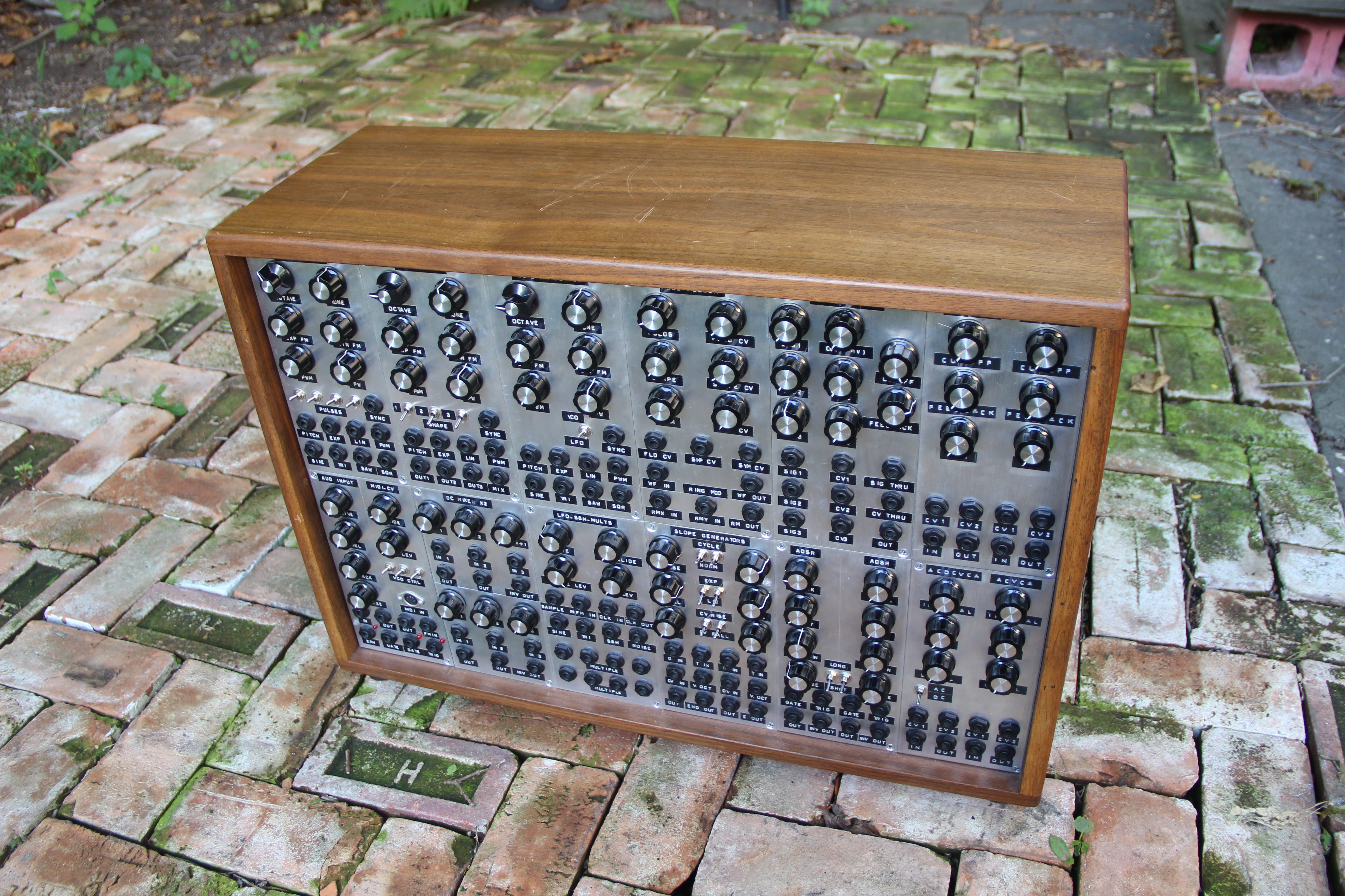
modular analog synthesizer for a.p.
Slope generators is an open-source printed circuit board by JordanAceto, from the JordanAceto/angelo_modular repository on GitHub, published under the CC-BY-4.0 licence. It is a 2-layer board of 99.1 × 99.1 mm with 163 parts on 105 nets, routed with 924 tracks and 231 vias.
It is built around the TL072, LM3900D and MMBT3904, with the MMBT3906 among its other parts. Its parts include 90 resistors, 22 capacitors, 16 diodes, 12 transistors and 6 ICs.


/user_manuals/ directory. This directory also contains a document outlining any pcb kludges or changes to the current system./pcb_docs/ directoryA very brief README outlining the basics of the pcb
/construction_docs/ subdirectory which contains:
/kicad_docs/ subdirectory which contains the files needed to edit the schematic and pcb layout with kicad
/pics/ subdirectory which contains a few rendered pictures of the pcb for reference
| Qty | Value | Footprint | References |
|---|---|---|---|
| 24 | 100k | Resistor_SMD:R_0805_2012Metric_Pad1.15x1.40mm_HandSolder | R2, R3, R4, R10, R15, R17, R28, R30, R47, R48, R49, R51, R52, R53, R54, R55 +8 |
| 12 | D | Diode_SMD:D_SOD-123 | D1, D2, D3, D4, D5, D7, D9, D10, D11, D12, D13, D15 |
| 10 | 100nF | Capacitor_SMD:C_0805_2012Metric_Pad1.15x1.40mm_HandSolder | C6, C7, C8, C9, C10, C11, C12, C13, C14, C15 |
| 8 | 220k | Resistor_SMD:R_0805_2012Metric_Pad1.15x1.40mm_HandSolder | R23, R26, R27, R34, R68, R71, R72, R79 |
| 8 | 33k | Resistor_SMD:R_0805_2012Metric_Pad1.15x1.40mm_HandSolder | R11, R12, R13, R14, R56, R57, R58, R59 |
| 6 | 100k | Potentiometer_THT:Potentiometer_Alpha_RD901F-40-00D_Single_Vertical | RV1, RV2, RV3, RV5, RV6, RV7 |
| 6 | 2k2 | Resistor_SMD:R_0805_2012Metric_Pad1.15x1.40mm_HandSolder | R31, R32, R41, R76, R77, R86 |
| 6 | 82k | Resistor_SMD:R_0805_2012Metric_Pad1.15x1.40mm_HandSolder | R18, R21, R29, R63, R66, R74 |
| 6 | MMBT3904 | Package_TO_SOT_SMD:SOT-23_Handsoldering | Q3, Q5, Q6, Q9, Q11, Q12 |
| 6 | MMBT3906 | Package_TO_SOT_SMD:SOT-23_Handsoldering | Q1, Q2, Q4, Q7, Q8, Q10 |
| 4 | 10M | Resistor_SMD:R_0805_2012Metric_Pad1.15x1.40mm_HandSolder | R35, R38, R80, R83 |
| 4 | 1M | Resistor_SMD:R_0805_2012Metric_Pad1.15x1.40mm_HandSolder | R39, R40, R84, R85 |
| 4 | 1k | Resistor_SMD:R_0805_2012Metric_Pad1.15x1.40mm_HandSolder | R42, R45, R87, R90 |
| 4 | 1nF | Capacitor_SMD:C_0805_2012Metric_Pad1.15x1.40mm_HandSolder | C1, C2, C18, C19 |
| 4 | 47k | Resistor_SMD:R_0805_2012Metric_Pad1.15x1.40mm_HandSolder | R19, R20, R64, R65 |
| 4 | 47pF | Capacitor_SMD:C_0805_2012Metric_Pad1.15x1.40mm_HandSolder | C3, C4, C20, C21 |
| 4 | 560k | Resistor_SMD:R_0805_2012Metric_Pad1.15x1.40mm_HandSolder | R5, R16, R50, R61 |
| 4 | 820k | Resistor_SMD:R_0805_2012Metric_Pad1.15x1.40mm_HandSolder | R22, R24, R67, R69 |
| 4 | TL072 | Package_SO:SOIC-8_3.9x4.9mm_P1.27mm | U1, U2, U4, U5 |
| 2 | 100 | Resistor_SMD:R_0805_2012Metric_Pad1.15x1.40mm_HandSolder | R43, R88 |
| 2 | 100k | Potentiometer_THT:Potentiometer_Bourns_3296W_Vertical | RV4, RV8 |
| 2 | 10uF | Capacitor_THT:CP_Radial_D6.3mm_P2.50mm | C16, C17 |
| 2 | 150k | Resistor_SMD:R_0805_2012Metric_Pad1.15x1.40mm_HandSolder | R44, R89 |
| 2 | 1k8 | Resistor_SMD:R_0805_2012Metric_Pad1.15x1.40mm_HandSolder | R33, R78 |
| 2 | 22nF | Capacitor_SMD:C_0805_2012Metric_Pad1.15x1.40mm_HandSolder | C5, C22 |
| 2 | 270k | Resistor_SMD:R_0805_2012Metric_Pad1.15x1.40mm_HandSolder | R1, R46 |
| 2 | 330k | Resistor_SMD:R_0805_2012Metric_Pad1.15x1.40mm_HandSolder | R37, R82 |
| 2 | 5v6 | Diode_SMD:D_SOD-123 | D6, D14 |
| 2 | 68k | Resistor_SMD:R_0805_2012Metric_Pad1.15x1.40mm_HandSolder | R25, R70 |
| 2 | 8k2 | Resistor_SMD:R_0805_2012Metric_Pad1.15x1.40mm_HandSolder | R36, R81 |
| 2 | LED | LED_THT:LED_D5.0mm | D8, D16 |
| 2 | LM3900 | Package_SO:SOIC-14_3.9x8.7mm_P1.27mm | U3, U6 |
| 2 | auto_cycle_switch | slope_generators:SPDT_on_on | SW2, SW5 |
| 2 | lin_expo_switch | slope_generators:SPDT_on_on | SW1, SW4 |
| 2 | rise-fall-both-switch | slope_generators:SPDT_on_on | SW3, SW6 |
| 1 | power_in | Connector_PinHeader_2.54mm:PinHeader_2x05_P2.54mm_Vertical | J3 |
| 1 | slope_1_port | Connector_PinHeader_2.54mm:PinHeader_1x07_P2.54mm_Vertical | J1 |
| 1 | slope_2_port | Connector_PinHeader_2.54mm:PinHeader_1x07_P2.54mm_Vertical | J2 |


JordanAceto/angelo_modular
modular analog synthesizer for a.p.

JordanAceto/VCF_plug_in_boards
Various small synthesizer Voltage Controlled Filter pcbs


masonandrewmann/modular-synth-pcbs
these are some pcbs :~)


mzuelch/CATs-Eurosynth
Analog Synth Eurorack Modules

dvhx/smd-soldering-exercise-0805
Ultimate SMD soldering exercise full of 0805 resistor and caps, SOT-23 transistors and SOIC-8 opamps - 23 guitar pedals on one 10x10cm PCB.

JordanAceto/modulation_source
Eurorack compatible pcb with sine/square VCLFO, white and pink noise, and sample & hold

It measures 99.1 × 99.1 mm and has 2 copper layers, 1.6 mm thick.
163 parts, built around the TL072, LM3900D, MMBT3904 and MMBT3906. The full list of its parts is on this page, with links to each part's symbol and footprint where PCBKit's library has them.
From the JordanAceto/angelo_modular repository on GitHub, at the commit this page was made from: the board is pcb_docs/slope_generators/kicad_docs/slope_generators.kicad_pcb. PCBKit opens the board in the browser, with nothing to install.
Its repository publishes it under the CC-BY-4.0 licence: you may reuse it on that licence's terms (keep the author's notice, and for a copyleft licence share your changes alike).