2 layers190 × 75 mm
Q17-TURBO
stefaweb/Q17-Amplifier
The Q17 is an error correction HIFI amplifier based on the QUAD405 current dumping principle.
109 parts25GPL-3.0

 JeanOlivier/LED_Dimmer_12V
PWM LED Dimmer built around a 555 timer. Designed for 12V+ power supply and using a CMOS transistor to support high power draw.
LED Dimmer 12V is an open-source printed circuit board by JeanOlivier, from the JeanOlivier/LED_Dimmer_12V repository on GitHub, published under the GPL-3.0 licence. It is a 2-layer board of 37.5 × 20.3 mm with 10 parts on 9 nets, routed with 40 tracks and 0 vias.
It is built around the NE555 and IRF610. Its parts include 2 capacitors, 2 diodes, 1 resistor and 1 IC. It belongs with the power and lEDs and displays boards of this library.


A pulse width modulation (PWM) LED Dimmer built around a 555 timer. Designed for 12V+ power supply (but should work for 5V+) and using a CMOS transistor to support high power draw.
The 555 part is inspired by this circuit.
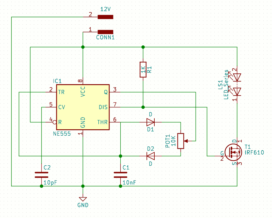
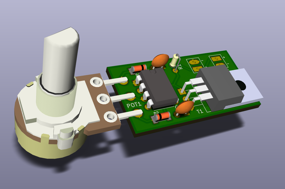
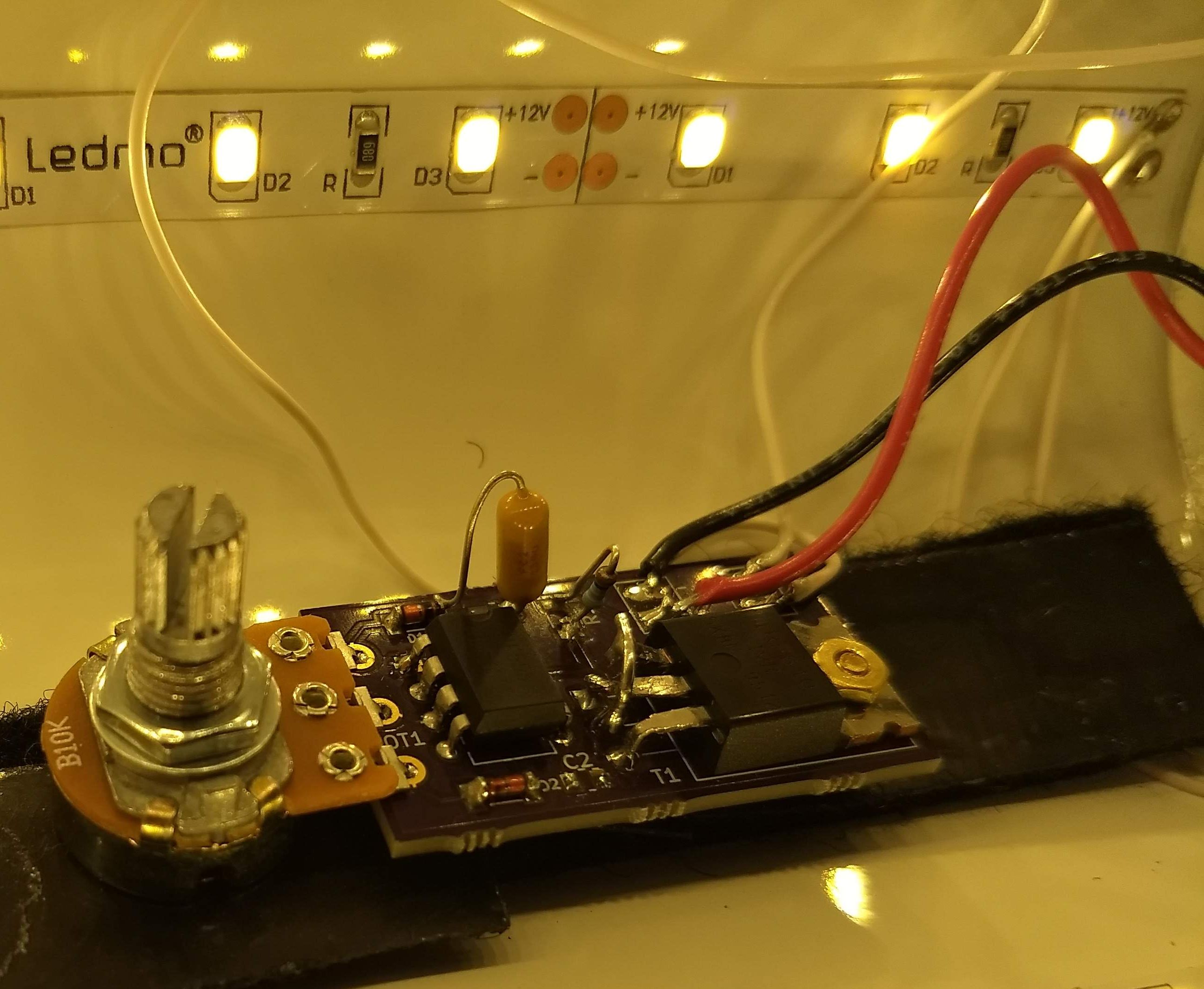
| Qty | Value | Footprint | References |
|---|---|---|---|
| 2 | D | Diodes_SMD:sod80c | D1, D2 |
| 1 | 10K | Resistors_THT:R_Axial_DIN0204_L3.6mm_D1.6mm_P1.90mm_Vertical | R1 |
| 1 | 10K | Potentiometers:Potentiometer_Alps_RK163_Single_Vertical | POT1 |
| 1 | 10nF | Capacitors_THT:C_Disc_D5.0mm_W2.5mm_P2.50mm | C1 |
| 1 | 10pF | Capacitors_THT:C_Disc_D5.0mm_W2.5mm_P2.50mm | C2 |
| 1 | 12V | Connectors:PINHEAD1-2 | 12V |
| 1 | IRF610 | TO_SOT_Packages_THT:TO-220_Horizontal | T1 |
| 1 | LED_Series | Connectors:PINHEAD1-2 | LEDS |
| 1 | NE555 | Housings_DIP:DIP-8_W7.62mm | IC1 |
stefaweb/Q17-Amplifier
The Q17 is an error correction HIFI amplifier based on the QUAD405 current dumping principle.


currawong-project/picadae
Project files for the Currawong Picadae piano player mechanism


It measures 37.5 × 20.3 mm and has 2 copper layers, 1.6 mm thick.
10 parts, built around the NE555 and IRF610. The full list of its parts is on this page, with links to each part's symbol and footprint where PCBKit's library has them.
From the JeanOlivier/LED_Dimmer_12V repository on GitHub, at the commit this page was made from: the board is LED_Dimmer_12V.kicad_pcb. PCBKit opens the board in the browser, with nothing to install.
Its repository publishes it under the GPL-3.0 licence: you may reuse it on that licence's terms (keep the author's notice, and for a copyleft licence share your changes alike).