2 layers354 × 295.1 mm
SV PWM card R01
mariusenglund/three-phase-inverter
Materials for enhancing the DC-to-AC converter that was designed as part of our bachelor's thesis in the spring of 2023.
257 parts2GPL-3.0
 JanBotnen/Three-phase-inverter_Modification
Design and implementation of a three-phase inverter with SPWM and SVPWM, prepared for future PMSM control.
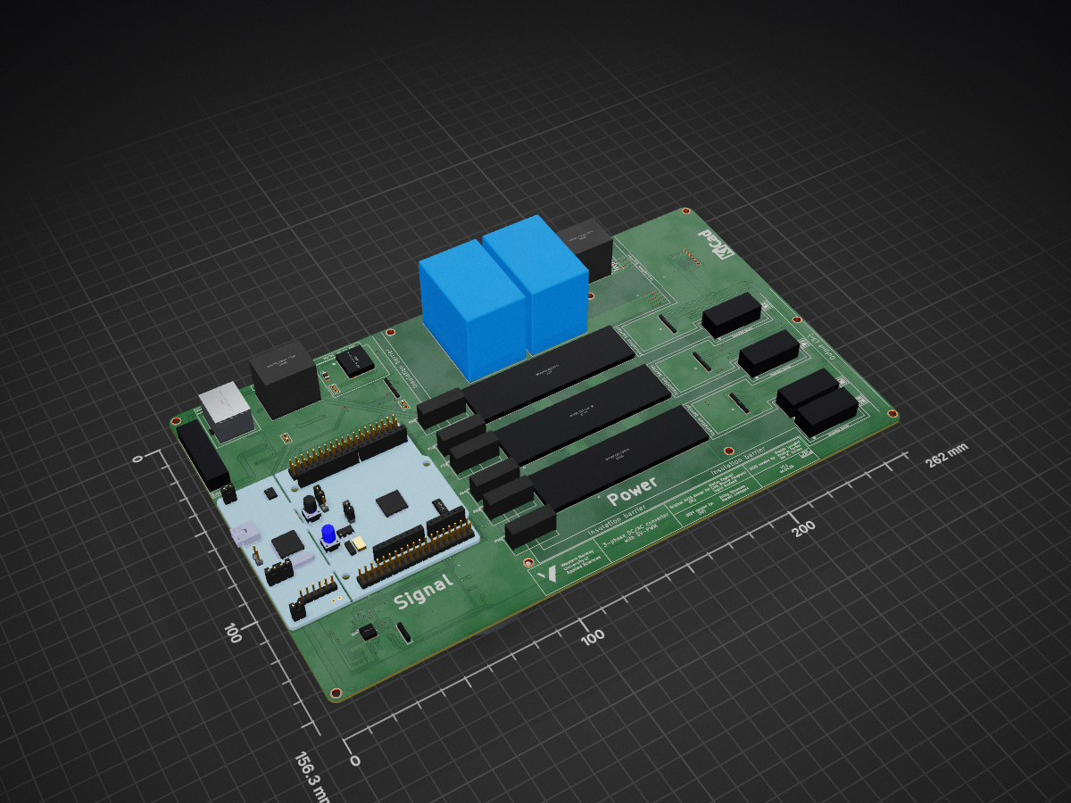
SV PWM card R01 is an open-source printed circuit board by JanBotnen, from the JanBotnen/Three-phase-inverter_Modification repository on GitHub, published under the GPL-3.0 licence. It is a 2-layer board of 262 × 156.3 mm with 223 parts on 196 nets, routed with 2,771 tracks and 377 vias.
It is built around the MGJ2D241509SC, NTE0505MC and TLI4971A050T5UE0001XUMA1, with the ACPL-C87B-000E, MAX14890EATJ+T and TBP03R1-350-09GR among its other parts. Its parts include 69 resistors, 57 capacitors, 28 ICs, 22 connectors and 12 diodes.


Download the KiCad project from this location.
Be aware that the files are still a work in progress.
| Qty | Value | Footprint | References |
|---|---|---|---|
| 23 | 4.7k | Resistor_SMD:R_1206_3216Metric_Pad1.30x1.75mm_HandSolder | R1, R2, R3, R4, R13, R13, R14, R14, R19, R19, R20, R20, R32, R35, R36, R42 +7 |
| 13 | 5019 | SVPWM-LIB-footprints:Keystone-5019 | J11, J12, J13, J13, J14, J15, J16, J17, J18, J19, J20, J21, J22 |
| 13 | R | Resistor_SMD:R_1206_3216Metric_Pad1.30x1.75mm_HandSolder | R37, R38, R39, R40, R48, R49, R50, R51, R56, R57, R58, R59, R60 |
| 12 | 1u | Capacitor_SMD:C_1206_3216Metric_Pad1.33x1.80mm_HandSolder | C15, C16, C17, C18, C23, C24, C25, C26, C31, C32, C33, C34 |
| 11 | 100n | Capacitor_SMD:C_1206_3216Metric_Pad1.33x1.80mm_HandSolder | C2_B1, C3_B1, C4_B1, C5_B1, C13, C14, C21, C22, C29, C30, C47 |
| 10 | MountingHole | FootprintLib_ErlingOgHaraldV24:Skru-hull_3mm | H6, H6, H6, H7, H7, H7, H7, H7, H7, H8 |
| 8 | 1k | Resistor_SMD:R_1206_3216Metric_Pad1.30x1.75mm_HandSolder | R10, R12, R16, R18, R22, R24, R25, R26 |
| 8 | 1n | Capacitor_SMD:C_1206_3216Metric_Pad1.33x1.80mm_HandSolder | C7, C8, C9, C10, C11, C12, C53, C54 |
| 6 | 10 | Resistor_SMD:R_1206_3216Metric_Pad1.30x1.75mm_HandSolder | R9, R11, R15, R17, R21, R23 |
| 6 | 10k | Resistor_SMD:R_1206_3216Metric_Pad1.30x1.75mm_HandSolder | R5, R6, R52, R53, R54, R55 |
| 6 | 220p | Capacitor_SMD:C_1206_3216Metric_Pad1.33x1.80mm_HandSolder | C19, C20, C27, C28, C35, C36 |
| 6 | 6.8n | Capacitor_SMD:C_1206_3216Metric_Pad1.33x1.80mm_HandSolder | C37, C38, C42, C43, C44, C52 |
| 6 | D | SVPWM-LIB-footprints:Diode-SMBJ50CA | D3, D4, D7, D8, D11, D12 |
| 6 | D_Schottky | SVPWM-LIB-footprints:Schottky-BAT165AX | D1, D2, D5, D6, D9, D10 |
| 6 | MGJ2D241509SC | Converter_DCDC:Converter_DCDC_Murata_MGJ2DxxxxxxSC_THT | PS1, PS2, PS3, PS4, PS5, PS6 |
| 5 | SolderJumper_2_Open | Jumper:SolderJumper-2_P1.3mm_Open_Pad1.0x1.5mm | JP1, JP2, JP3, JP4, JP5 |
| 4 | 15n | Capacitor_SMD:C_1206_3216Metric_Pad1.33x1.80mm_HandSolder | C39, C40, C41, C51 |
| 4 | 220 | Resistor_SMD:R_1206_3216Metric_Pad1.30x1.75mm_HandSolder | R27, R28, R29, R41 |
| 4 | 220n | Capacitor_SMD:C_1206_3216Metric_Pad1.33x1.80mm_HandSolder | C4, C5, C6, C50 |
| 4 | ??? | Resistor_SMD:R_1206_3216Metric_Pad1.30x1.75mm_HandSolder | R_DC-link_1, R_DC-link_2, R_DC-link_3, R_DC-link_4 |
| 4 | TLI4971A050T5UE0001XUMA1 | SVPWM-LIB-footprints:TLI4971A050T5UE0001XUMA1 | U8, U9, U10, U16 |
| 4 | WAGO_2606-1101 | _Library_Nytt:CONN_2606-1101_WAG | J1, J2, J3, J4 |
| 3 | 100p | Capacitor_SMD:C_1206_3216Metric | C48, C49, C55 |
| 3 | 270 | Resistor_SMD:R_1206_3216Metric | R61, R62, R63 |
| 3 | 500k | Resistor_SMD:R_1206_3216Metric_Pad1.30x1.75mm_HandSolder | R1_B1, R2_B1, R3_B1 |
| 3 | Conn_01x02_Male | Connector_PinHeader_2.54mm:PinHeader_1x02_P2.54mm_Vertical | J6, J9, J10 |
| 3 | Infineon_2ED020I12-F2 | SVPWM-LIB-footprints:GateDriver-2ED020I12F2XUMA1 | U11, U12, U13 |
| 2 | , | ||
| 2 | 14u | SVPWM-LIB-footprints:DC-link-capacitor-B32776G0146K000 | C_dc-link1, Cdc_link2 |
| 2 | 16.5k | Resistor_SMD:R_1206_3216Metric_Pad1.30x1.75mm_HandSolder | R44, R45 |
| 2 | LOGO | HVL_logo:HVL_logo | G***, G*** |
| 2 | Wago_2604-3104 | SVPWM-LIB-footprints:WAGO-26043104 | U4, U19 |
| 1 | 100p | Capacitor_SMD:C_1206_3216Metric_Pad1.33x1.80mm_HandSolder | C1_B1 |
| 1 | 10u | Capacitor_SMD:C_1206_3216Metric_Pad1.33x1.80mm_HandSolder | C2 |
| 1 | 22u | Capacitor_SMD:C_1206_3216Metric_Pad1.33x1.80mm_HandSolder | C3 |
| 1 | 2606-1106/010-000 | _Library_Nytt:6PinHeaderConnector_Strømsensor | J23 |
| 1 | 3.75k | Resistor_SMD:R_1206_3216Metric_Pad1.30x1.75mm_HandSolder | R4_B1 |
| 1 | 4.7u | Capacitor_SMD:C_1206_3216Metric_Pad1.33x1.80mm_HandSolder | C_BYP1 |
| 1 | 47u | Inductor_SMD:L_2010_5025Metric_Pad1.52x2.65mm_HandSolder | L1 |
| 1 | ACPL-C87B-000E | SVPWM-LIB-footprints:ACPL-SOIC127P1150X331-8N | U2 |
| 1 | Inverter leg nr 1 | FootprintLib_ErlingOgHaraldV24:Inverter leg | U5 |
| 1 | Inverter leg nr 2 | FootprintLib_ErlingOgHaraldV24:Inverter leg | U14 |
| 1 | Inverter leg nr 3 | FootprintLib_ErlingOgHaraldV24:Inverter leg | U15 |
| 1 | MAX14890EATJ+T | _Library_Nytt:21-0140_T3255&plus_6_MXM_Encoder_chip | U18 |
| 1 | MCU | FootprintLib_ErlingOgHaraldV24:MODULE_NUCLEO-L476RG | U1 |
| 1 | MP-K7805T-500R3 | _Library_Nytt:TRN 1&slash_3SM_SINGLE_TRP | U6 |
| 1 | NTE0505MC | SVPWM-LIB-footprints:DC-DC-NTE0505MC | PS7 |
| 1 | PinConector_DC-link | FootprintLib_ErlingOgHaraldV24:6PinHeaderConnector_Strømsensor | U36 |
| 1 | PinConector_MCU-til-L1 | FootprintLib_ErlingOgHaraldV24:6PinHeaderConnector_Strømsensor | U40 |
| 1 | PinConnector_L1-sensor | FootprintLib_ErlingOgHaraldV24:6PinHeaderConnector_Strømsensor | U37 |
| 1 | PinConnector_L2-sensor | FootprintLib_ErlingOgHaraldV24:6PinHeaderConnector_Strømsensor | U38 |
| 1 | PinConnector_L3-sensor | FootprintLib_ErlingOgHaraldV24:6PinHeaderConnector_Strømsensor | U39 |
| 1 | PinConnector_MCU-til-DClink | FootprintLib_ErlingOgHaraldV24:6PinHeaderConnector_Strømsensor | U43 |
| 1 | PinConnector_MCU-til-L2 | FootprintLib_ErlingOgHaraldV24:6PinHeaderConnector_Strømsensor | U41 |
| 1 | PinConnector_MCU-til-L3 | FootprintLib_ErlingOgHaraldV24:6PinHeaderConnector_Strømsensor | U42 |
| 1 | RJ45_Connector_MCU-til-HMI | Connector_RJ:RJ45_Amphenol_54602-x08_Horizontal | U17 |
| 1 | SN54HCT245_BusTranciver | _Library_Nytt:ETSSOP-20-1EP_4.4x6.5mm_P0.65mm_EP3x4.2mm_ny123 | U44 |
| 1 | TBP03R1-350-09GR | _Library_Nytt:TBP03R1-350-03GR | J5 |
| 1 | TRN 1-2410SM | _Library_Nytt:TRN 1&slash_3SM_SINGLE_TRP | U7 |
| 1 | type="X" model="OPAMP" lib="" | _Library_Nytt:D8 | U3 |
The 222 most common of 223 parts.
mariusenglund/three-phase-inverter
Materials for enhancing the DC-to-AC converter that was designed as part of our bachelor's thesis in the spring of 2023.


louieoneil19/Thesis
Design and Control of a Solar-Powered Irrigation System for Remote Farmlands

MiniNugen/Custom_Inverter_Hardware
PCBProjectNameREV1.PrjPCB | Source Documents | | PCBProjectNameREV1.SchDOC | | PCBProjectNameREV1.PcbDOC | | BOM | Settings | Libraries


thebiguno/microcontroller-projects
A home for a bunch of microcontroller projects which don't warrant their own repos.

andykarpov/karabas-pro
FPGA based retrocomputer with FDD and HDD controllers
It measures 262 × 156.3 mm and has 2 copper layers, 1.6 mm thick.
223 parts, built around the MGJ2D241509SC, NTE0505MC, TLI4971A050T5UE0001XUMA1 and ACPL-C87B-000E. The full list of its parts is on this page, with links to each part's symbol and footprint where PCBKit's library has them.
From the JanBotnen/Three-phase-inverter_Modification repository on GitHub, at the commit this page was made from: the board is Main_project_file/Trefase_DC-til-AC_Omformer/pcb-design-files_v3/SV-PWM_card_R01.kicad_pcb and its schematic Main_project_file/Trefase_DC-til-AC_Omformer/pcb-design-files_v3/Braking.kicad_sch. PCBKit opens the board in the browser, with nothing to install.
Its repository publishes it under the GPL-3.0 licence: you may reuse it on that licence's terms (keep the author's notice, and for a copyleft licence share your changes alike).