4 layers49.3 × 51.8 mm
Mega
1vers1on/Mega
A microcontroller based on the RP2350B with a dedicated dac and adc, plus wifi and bluetooth.
52 parts

 Jameswill-Winsock/funkyboi
a funky chonky handheld gba clone
Funkyboi is an open-source printed circuit board by Jameswill-Winsock, from the Jameswill-Winsock/funkyboi repository on GitHub. It is a 4-layer board of 51 × 30 mm with 52 parts on 79 nets, routed with 1,024 tracks and 132 vias.
It is built around the RP2350B, W25Q128JVPIQ and BSS84. Its parts include 19 capacitors, 11 resistors, 9 connectors, 5 ICs and 2 diodes. It belongs with the RP2350 boards of this library.


a funky chonky handheld gba clone
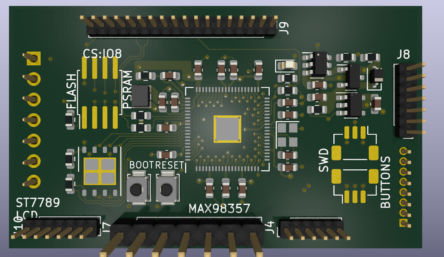
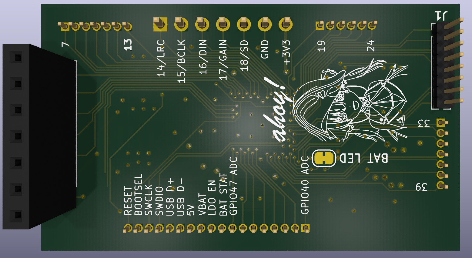
he's a work in progress, please bear with him
like you read, a gba clone. its meant to be as small in form factor as possible, and currently i've nearly achieved this. it borrows from the solderparty stamp xl in form of the schematic, but pcb was remade because it wouldn't open for me for some reason. some differences between those and this are:
please refer to "BOM reference.csv". Has everything for now,
included please check
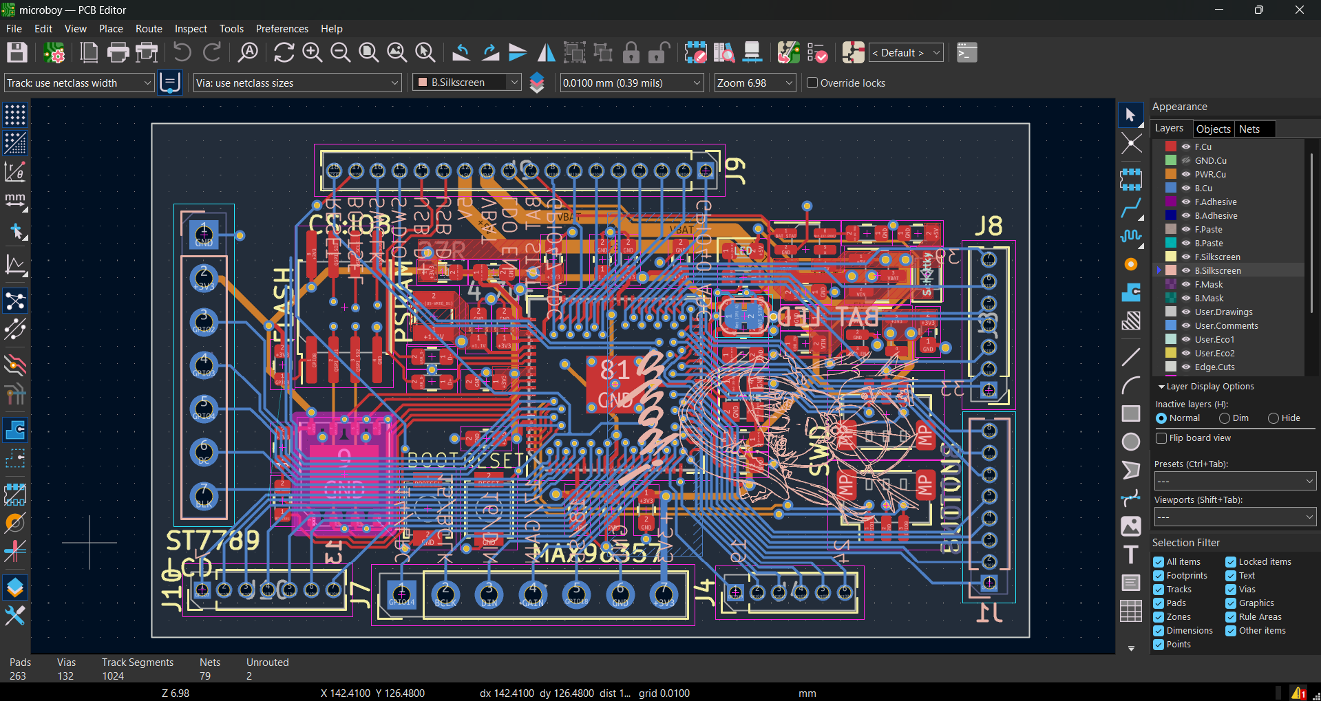
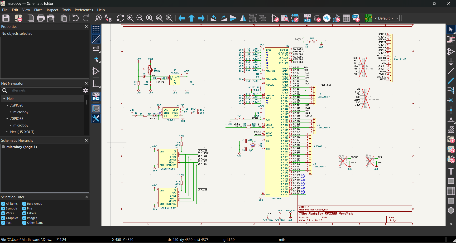
yes i know the elephant in the room is the big red cross marks they're marked do not populate because i want to leave the headers alone until i need them and for the actual parts that'll be needed i'll hand solder what i can
to you for coming here
| Qty | Value | Footprint | References |
|---|---|---|---|
| 11 | 0.1uF | Capacitor_SMD:C_0603_1608Metric | C6, C7, C8, C9, C10, C11, C13, C15, C17, C18, C19 |
| 5 | 100K | Resistor_SMD:R_0603_1608Metric | R1, R3, R4, R8, R10 |
| 4 | 10uF | Capacitor_SMD:C_0603_1608Metric | C1, C2, C3, C16 |
| 3 | 27R | Resistor_SMD:R_0603_1608Metric | R6, R7, R11 |
| 3 | 2K | Resistor_SMD:R_0603_1608Metric | R2, R5, R9 |
| 2 | 12pF | Capacitor_SMD:C_0603_1608Metric | C4, C5 |
| 2 | 4.7uF | Capacitor_SMD:C_0603_1608Metric | C12, C14 |
| 2 | Conn_01x07 | Connector_PinHeader_1.27mm:PinHeader_1x07_P1.27mm_Vertical | J8, J10 |
| 1 | 3.3uH | Inductor_SMD:L_Wuerth_MAPI-2512 | L1 |
| 1 | BSS84 | Package_TO_SOT_SMD:SOT-23 | Q1 |
| 1 | BUTTONS | Connector_PinHeader_1.27mm:PinHeader_1x08_P1.27mm_Vertical | J1 |
| 1 | CM4012M00012001 | Crystal:Crystal_SMD_2520-4Pin_2.5x2.0mm | Y1 |
| 1 | Conn_01x06 | Connector_PinHeader_1.27mm:PinHeader_1x06_P1.27mm_Vertical | J4 |
| 1 | Conn_01x18 | Connector_PinHeader_1.27mm:PinHeader_1x18_P1.27mm_Vertical | J9 |
| 1 | Conn_Pi_SWD | Connector_JST:JST_SH_BM03B-SRSS-TB_1x03-1MP_P1.00mm_Vertical | J5 |
| 1 | Conn_Pi_UART | Connector_JST:JST_SH_BM03B-SRSS-TB_1x03-1MP_P1.00mm_Vertical | J6 |
| 1 | D_Schottky_Small | Diode_SMD:D_SOD-323 | D1 |
| 1 | FLASH or PSRAM | Package_SO:SSOP-8_5.25x5.24mm_P1.27mm | U4 |
| 1 | LED_CHR | LED_SMD:LED_0603_1608Metric | D2 |
| 1 | MAX98357 | Connector_PinHeader_2.54mm:PinHeader_1x07_P2.54mm_Vertical | J7 |
| 1 | ME4055 | Package_TO_SOT_SMD:SOT-23-6 | U2 |
| 1 | ME6211 | Package_TO_SOT_SMD:SOT-23-5 | U3 |
| 1 | RP2350B | Package_DFN_QFN_Extra:QFN-80_EP_10x10_Pitch0.4mm | U5 |
| 1 | SJ_STAT_LED | Jumper:SolderJumper-2_P1.3mm_Bridged_RoundedPad1.0x1.5mm | JP1 |
| 1 | ST7789 | Connector_PinSocket_2.54mm:PinSocket_1x07_P2.54mm_Vertical | J2 |
| 1 | SW_BOOTSEL | Button_Switch_SMD:SW_SPST_B3U-1000P | SW2 |
| 1 | SW_RESET | Button_Switch_SMD:SW_SPST_B3U-1000P | SW1 |
| 1 | W25Q128JVPIQ | Package_SON:WSON-8-1EP_6x5mm_P1.27mm_EP3.4x4mm | U1 |
1vers1on/Mega
A microcontroller based on the RP2350B with a dedicated dac and adc, plus wifi and bluetooth.


elrir01/AudioPico
This board receive audio from a BT source like a phone and outputs via a DAC the audio. It's an old project of mine but I've decided to publish it just now, so the full description is not ready and will be updated in…


rh1tech/frank-lab
FRANK Board Laboratory (work-in-progress board prototopyes)


It measures 51 × 30 mm and has 4 copper layers, 1 mm thick.
52 parts, built around the RP2350B, W25Q128JVPIQ and BSS84. The full list of its parts is on this page, with links to each part's symbol and footprint where PCBKit's library has them.
From the Jameswill-Winsock/funkyboi repository on GitHub, at the commit this page was made from: the board is pcb/funkyboi.kicad_pcb and its schematic pcb/funkyboi.kicad_sch. PCBKit opens the board in the browser, with nothing to install.
Its repository states no licence, so its author keeps all rights: ask Jameswill-Winsock before reusing the design.