4 layers104 × 64 mm
 JS2028EE/ESP32_FC
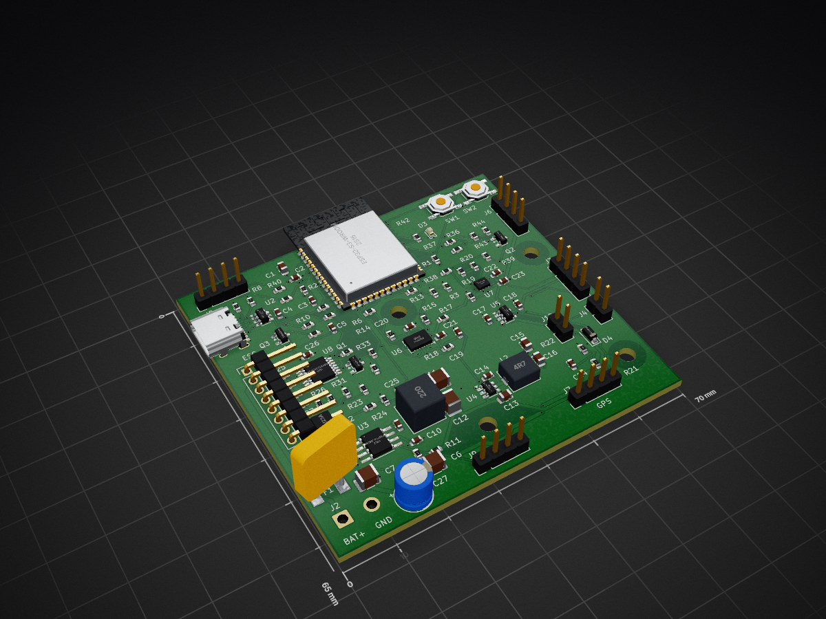
This is the current editable KiCad 10 project for a 70 x 65 mm, four-layer controller, with an ESP32-S3-WROOM-1-N8R8, BMI088 SPI IMU, BMP280 barometer and a separate 4-in-1 ESC.
ESP32 FC is an open-source printed circuit board by JS2028EE, from the JS2028EE/ESP32_FC repository on GitHub. It is a 4-layer board of 70 × 65 mm with 107 parts on 90 nets, routed with 1,470 tracks and 194 vias.
It is built around the ESP32-S3-WROOM-1-N8R8, SN74LVC125APWR-TP and BMP280, with the BMI088, TLV75533PDBVR-MS and USBLC6-2SC6 among its other parts. Its parts include 46 resistors, 27 capacitors, 10 connectors, 8 ICs and 4 diodes. It belongs with the ESP32 boards of this library.


This is the current editable KiCad 10 project for a 70 x 65 mm, four-layer controller, with an ESP32-S3-WROOM-1-N8R8, BMI088 SPI IMU, BMP280 barometer and a separate 4-in-1 ESC. The FC supply accepts a 3S-6S LiPo (9-25.2 V). Motor current stays on the ESC.
Order status: prepared for a small bare-board prototype run to Order_Instructions.md. This is an unbuilt design, not validated flight hardware. KiCad checks and the source/PCB audit pass. The manufacturer still must accept the uploaded fabrication data and requested stackup through its normal DFM process. Physical regulator, USB, sensor and flight validation cannot be completed in software. No flight firmware is included.
Use the Rev B ZIP and Gerbers. The earlier Rev A packages are superseded for this build.
Extract the entire project ZIP. Open ESP32_FC.kicad_pro, then ESP32_FC.kicad_sch or ESP32_FC.kicad_pcb. Keep all five schematic files and FC_Prototype.pretty together. In PCB Editor, Alt+3 opens the native 3D Viewer using installed KiCad 10 model libraries. A separate STEP assembly is not bundled. Some bodies are absent in the preview, including the USB connector and the new fuse; model availability does not affect the fabrication data. PCB_Preview.png is a partial 3D illustration, not an exact assembly envelope check.
| Function | ESP32-S3 GPIO | Notes |
|---|---|---|
| Battery ADC | 1 | ADC1; senses protected input after D1 |
| ESC current ADC | 2 | ADC1; 2:1 divider, 0-5 V analog input only |
| Motor 1 / 2 / 3 / 4 | 4 / 5 / 6 / 15 | Through U8 and 33-ohm series resistors |
| Gyro / accel data-ready | 7 / 8 | BMI088 INT3 / INT1 |
| Gyro / accel CS | 9 / 10 | Active low; external 10k pull-ups |
| IMU MOSI / SCK / MISO | 11 / 12 / 13 | Separate from the flash/PSRAM interface |
| USB VBUS sense | 16 | Active-low, isolated by Q3 |
| Receiver TX / RX | 17 / 18 | Flight-controller perspective; remapped UART1 |
| USB D- / D+ | 19 / 20 | 22-ohm series termination and USBLC6 protection |
| Arm output | 21 | HIGH enables motor buffers; LOW disables |
| I2C SDA / SCL | 38 / 39 | 4.7k pull-ups to sensor rail |
| Status LED | 40 | HIGH turns LED on |
| Auxiliary GPIO | 41 | Exposed on J9 |
| Active buzzer | 42 | Drives Q2; external 5 V active buzzer <=30 mA |
| Debug TX / RX | 43 / 44 | UART0; includes boot messages |
| GPS TX / RX | 47 / 48 | Remapped UART2 |
| Boot / voltage straps | 0 / 45 / 46 | Boot pull-up, GPIO45/46 pull-downs |
GPIO3 and GPIO14 are unused. GPIO35/36/37 are reserved. Critical sensor buffers and control code should use internal SRAM; do not depend on PSRAM access latency for the real-time loop. A reasonable initial firmware target is a 1 kHz gyro-triggered loop, subject to measured worst-case latency. Hardware peripherals should generate motor timing. Radio operation, flash writes, USB, and navigation tasks must be qualified for scheduling interference.
Connector_Pin_Map.csv gives every numbered header pad and its location as viewed from the component side, with the antenna at the top. It is the definitive pad-to-net map. J5 uses 2.54 mm headers, not the 1 mm connector fitted to commercial ESCs. A custom harness is required.
| Connector | Pins in numeric order |
|---|---|
| J2 | battery+, GND; FC branch supply only |
| J3 | GND, sensor 3.3V, SDA, SCL |
| J4 | ARM_GATE, GND; short to force outputs disabled |
| J5 | GND, battery+, motor1, motor2, motor3, motor4, analog current, telemetry breakout |
| J6 | GND, 5V, FC RX, FC TX; receiver |
| J7 | GND, 5V, FC RX, FC TX; GPS |
| J8 | GND, digital 3.3V, FC RX0, FC TX0; debug |
| J9 | GND, digital 3.3V, GPIO41, telemetry breakout |
| J10 | 5V, buzzer low-side drain |
J2 and J5 battery pins are the same node. Use only one FC battery feed. Receiver/GPS supply is 5 V but all MCU serial logic is 3.3 V. Do not connect independently powered serial devices or a 5 V UART adapter without checking powered-off and logic-voltage compatibility. J5 analog current accepts 0-5 V and divides it by two. Telemetry is only a passive breakout to J9, not a configured MCU UART.
The reference ESC is Holybro Tekko32 F4 4in1 50A AM32, SKU31102; see ESC_Wiring.md. It supports 4S-6S, so use a 4S pack for that reference combination. The FC itself retains its 3S-6S input range; using 3S requires an ESC explicitly rated for 3S. This recommendation does not establish motor/propeller compatibility; motor current requirements must be matched separately.
The 5 V regulator is rated 1 A; it supplies all downstream rails and peripherals. Initial allocations: digital 3.3 V <=0.70 A, sensor 3.3 V <=0.05 A, external 5 V <=0.25 A including buzzer. They correspond to about 0.84 A from 5 V at 85% digital-buck efficiency. These are design allocations, not measured continuous ratings. Begin bench tests with smaller loads and verify temperature and transients before approaching them. No VTX/air-unit supply is provided. External active buzzer <=30 mA.
The N8R8 module is specified by Espressif for ambient temperatures up to 65 C, which is lower than the 85 C rating of several passive parts. No board temperature operating range is qualified. Avoid inductors heating the sensors/module. Use the barometer without blocking its pressure port.
Q1 and U8 disable motor outputs during MCU reset. J4 is a physical disable strap. A frozen MCU that leaves ARM asserted is not stopped by independent watchdog hardware: firmware must configure watchdog reset, receiver timeout, arming checks, brownout handling and motor timing. Start with unidirectional DShot300 for ESC bring-up; bidirectional DShot is unsupported through U8. No stock Betaflight/PX4/ArduPilot binary is assumed to work on this custom ESP32 board.
Follow Assembly_and_Bringup.md. Solder paste and hot-air/reflow are required for the LGA sensors and exposed-pad regulator. Observe component moisture/reflow limits. All components mount on the front; C27 and headers are soldered after reflow. The 6.3 mm diameter C27 body is 11.2 mm tall. Inspect soldering and check resistance to ground before using a current-limited bench supply. Fit the kill strap; leave ESC, motors, receiver and GPS disconnected initially.
See Sources.md for manufacturer documents used for this revision, Order_Instructions.md for fabrication settings and Validation.md for the actual checks and their limits.
| Qty | Value | Footprint | References |
|---|---|---|---|
| 13 | 10k | Resistor_SMD:R_0603_1608Metric | R1, R2, R3, R4, R9, R17, R18, R22, R23, R24, R33, R45, R46 |
| 11 | 100n | Capacitor_SMD:C_0603_1608Metric | C2, C4, C10, C14, C19, C20, C22, C23, C24, C25, C26 |
| 8 | 33R | Resistor_SMD:R_0603_1608Metric | R13, R14, R15, R16, R25, R26, R27, R28 |
| 7 | 1k | Resistor_SMD:R_0603_1608Metric | R34, R36, R37, R39, R41, R42, R43 |
| 4 | 22u | Capacitor_SMD:C_0805_2012Metric | C1, C13, C15, C16 |
| 4 | 47k | Resistor_SMD:R_0603_1608Metric | R29, R30, R31, R32 |
| 4 | MountingHole_3.2mm_M3 | MountingHole_3.2mm_M3 | H1, H2, H3, H4 |
| 3 | 100k | Resistor_SMD:R_0603_1608Metric | R10, R35, R44 |
| 3 | DMN2056U | Package_TO_SOT_SMD:SOT-23 | Q1, Q2, Q3 |
| 2 | 100R | Resistor_SMD:R_0603_1608Metric | R38, R40 |
| 2 | 1u | Capacitor_SMD:C_0603_1608Metric | C3, C17 |
| 2 | 2.2u / 100V | Capacitor_SMD:C_1210_3225Metric | C6, C7 |
| 2 | 22R | Resistor_SMD:R_0603_1608Metric | R5, R6 |
| 2 | 22u / 25V | Capacitor_SMD:C_1210_3225Metric | C11, C12 |
| 2 | 4.7k | Resistor_SMD:R_0603_1608Metric | R19, R20 |
| 2 | 4.7u | Capacitor_SMD:C_0603_1608Metric | C18, C21 |
| 2 | 5.1k | Resistor_SMD:R_0603_1608Metric | R7, R8 |
| 1 | 10n | Capacitor_SMD:C_0603_1608Metric | C5 |
| 1 | 150k | Resistor_SMD:R_0603_1608Metric | R21 |
| 1 | 1A / 476 | FC_Prototype:Fuse_Littelfuse_476 | F1 |
| 1 | 1N4148W | Diode_SMD:D_SOD-123 | D4 |
| 1 | 1u / 16V | Capacitor_SMD:C_0603_1608Metric | C9 |
| 1 | 20k | Resistor_SMD:R_0603_1608Metric | R12 |
| 1 | 220n / 100V | Capacitor_SMD:C_0805_2012Metric | C8 |
| 1 | 22uH | Inductor_SMD:L_Bourns_SRP6060FA | L1 |
| 1 | 4-IN-1 ESC | Connector_PinHeader_2.54mm:PinHeader_1x08_P2.54mm_Vertical | J5 |
| 1 | 4.7uH | Inductor_SMD:L_Bourns_SRP5030T | L2 |
| 1 | 47u / 50V | Capacitor_THT:CP_Radial_D6.3mm_P2.50mm | C27 |
| 1 | 80.6k | Resistor_SMD:R_0603_1608Metric | R11 |
| 1 | ACTIVE BUZZER | Connector_PinHeader_2.54mm:PinHeader_1x02_P2.54mm_Vertical | J10 |
| 1 | AP63203WU-7 | Package_TO_SOT_SMD:TSOT-23-6 | U4 |
| 1 | AUX GPIO / TELEMETRY | Connector_PinHeader_2.54mm:PinHeader_1x04_P2.54mm_Vertical | J9 |
| 1 | BATTERY 3S-6S | Connector_Wire:SolderWire-1sqmm_1x02_P5.4mm_D1.4mm_OD2.7mm | J2 |
| 1 | BMI088 | Package_LGA:Bosch_LGA-16_4.5x3mm_P0.5mm_LayoutBorder7x1y_ClockwisePinNumbering | U6 |
| 1 | BMP280 | FC_Prototype:BMP280_SilkClear | U7 |
| 1 | BOOT | Button_Switch_SMD:SW_SPST_TL3342 | SW2 |
| 1 | CRSF RECEIVER | Connector_PinHeader_2.54mm:PinHeader_1x04_P2.54mm_Vertical | J6 |
| 1 | DEBUG UART0 | Connector_PinHeader_2.54mm:PinHeader_1x04_P2.54mm_Vertical | J8 |
| 1 | ESP32-S3-WROOM-1-N8R8 | FC_Prototype:ESP32_S3_WROOM_Edge | U1 |
| 1 | GPS UART | Connector_PinHeader_2.54mm:PinHeader_1x04_P2.54mm_Vertical | J7 |
| 1 | GREEN | LED_SMD:LED_0603_1608Metric | D3 |
| 1 | I2C / 3.3V ONLY | Connector_PinHeader_2.54mm:PinHeader_1x04_P2.54mm_Vertical | J3 |
| 1 | KILL STRAP | Connector_PinHeader_2.54mm:PinHeader_1x02_P2.54mm_Vertical | J4 |
| 1 | LMR36510ADDAR | Package_SO:Texas_HTSOP-8-1EP_3.9x4.9mm_P1.27mm_EP2.95x4.9mm_Mask2.4x3.1mm_ThermalVias | U3 |
| 1 | RESET | Button_Switch_SMD:SW_SPST_TL3342 | SW1 |
| 1 | SMBJ28A | Diode_SMD:D_SMB | D2 |
| 1 | SN74LVC125APWR | Package_SO:TSSOP-14_4.4x5mm_P0.65mm | U8 |
| 1 | SS310 / 100V 3A | Diode_SMD:D_SMA | D1 |
| 1 | TLV75533PDBVR | Package_TO_SOT_SMD:SOT-23-5 | U5 |
| 1 | USB-C / USB2 FS | FC_Prototype:USB_C_HRO_Edge | J1 |
| 1 | USBLC6-2SC6 | Package_TO_SOT_SMD:SOT-23-6 | U2 |

Bruhdows/klink
Klink is a magnetic tile system for building programmable machines. First up: a marble run with sensors, buttons, lights, gates, splitters and an elevator.

DD1SB/ARDF-TX
Date: 2026-10-15. Engineering review only; unbuilt and unenergized. Open RF80.kicadpro, schematic and native PCB in KiCad10.0.6. Three primary PCBs and the separate VHF true-AM design are unchanged.

lindestad/wind-controller
LINDESTAD simracing wind controller: ESP32-C3 Zephyr firmware, KiCad PCB and SimHub integration


dudgeon/count-fidget
A lightweight, rechargeable two-key fidget that counts clicks, resets with a second key, and remembers its count while asleep or unpowered. Designed for a home-printed enclosure and professionally assembled electronics.

nikolajevs/ai
Открыть PCBV1.kicadpro в KiCad 10. После обновления репозитория перечитать открытый проект с диска перед сохранением.

It measures 70 × 65 mm and has 4 copper layers, 1.6 mm thick.
107 parts, built around the ESP32-S3-WROOM-1-N8R8, SN74LVC125APWR-TP, BMP280 and BMI088. The full list of its parts is on this page, with links to each part's symbol and footprint where PCBKit's library has them.
From the JS2028EE/ESP32_FC repository on GitHub, at the commit this page was made from: the board is hardware/revB/ESP32_FC.kicad_pcb and its schematic hardware/revB/Auxiliary.kicad_sch. PCBKit opens the board in the browser, with nothing to install.
Its repository states no licence, so its author keeps all rights: ask JS2028EE before reusing the design.