2 layers9.9 × 27.6 mm
50mil IF D91B breakout
JKTsDoodles/ModuBits
This is a versatile set of prototyping boards and modules designed to fit chassis measuring 100mm wide and 120mm deep.
11 partsMIT

 JKTsDoodles/ModuBits
This is a versatile set of prototyping boards and modules designed to fit chassis measuring 100mm wide and 120mm deep. Each module allows for easy integration of various connectors and components, enabling efficient prototyping and experimentation in electronics projects.
50mil IF E96E breakout is an open-source printed circuit board by JKTsDoodles, from the JKTsDoodles/ModuBits repository on GitHub, published under the MIT licence. It is a 2-layer board of 10 × 26.9 mm with 14 parts on 18 nets, routed with 76 tracks and 5 vias.
Its parts include 4 capacitors, 3 resistors, 2 connectors, 1 IC and 1 diode. It belongs with the interfaces and adapters boards of this library.
This is a versatile set of prototyping boards and modules designed to fit chassis measuring 100mm wide and 120mm deep. Each module allows for easy integration of various connectors and components, enabling efficient prototyping and experimentation in electronics projects.
ECAD tool: KiCad 9.99 (nightly)
MCAD tool: FreeCAD 1.0.2
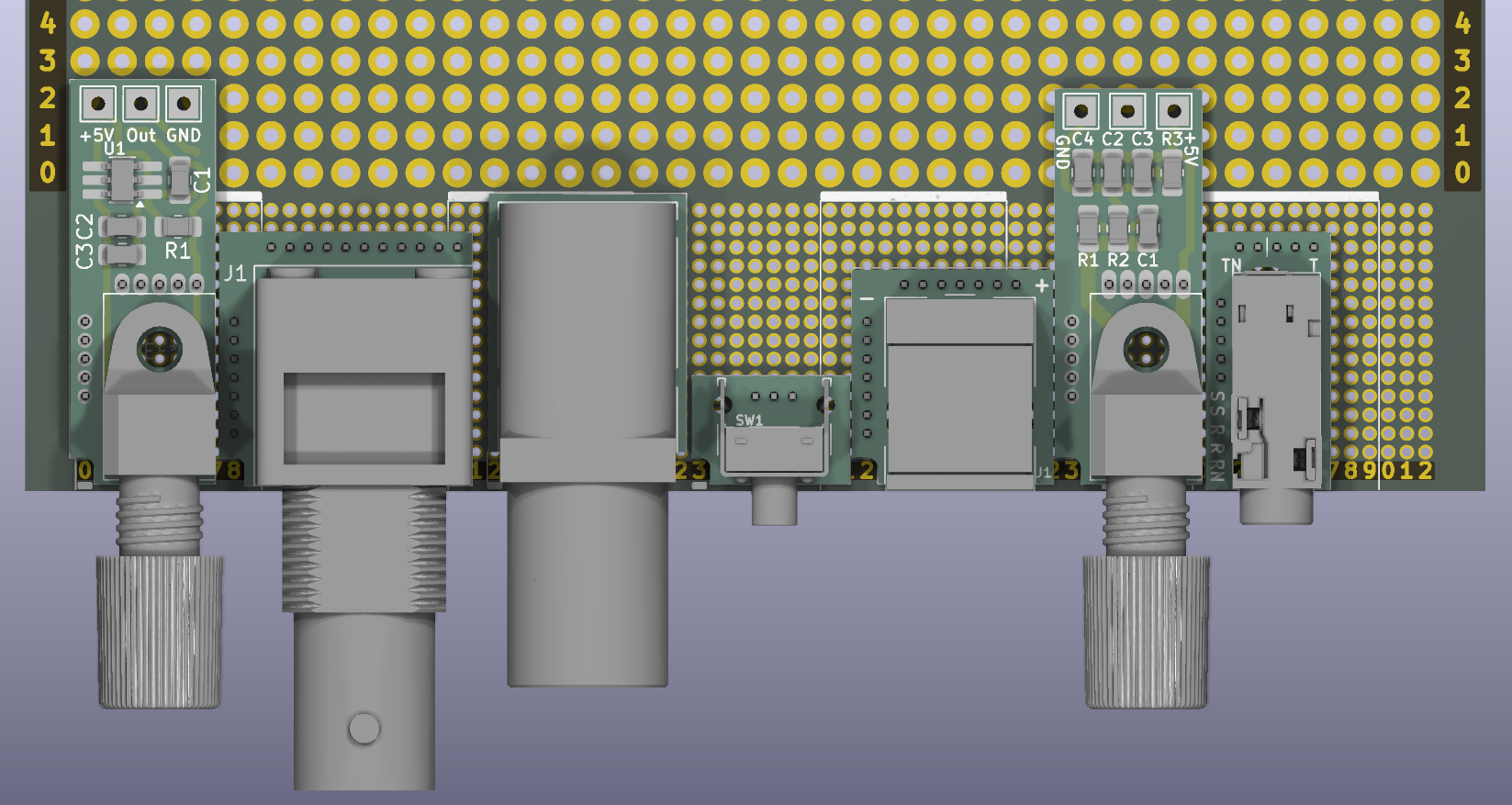
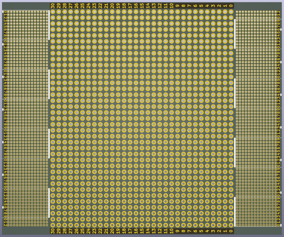
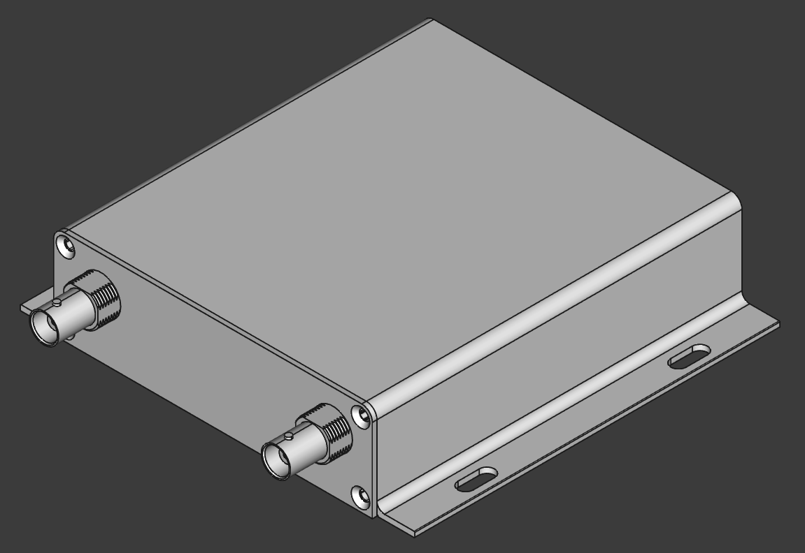
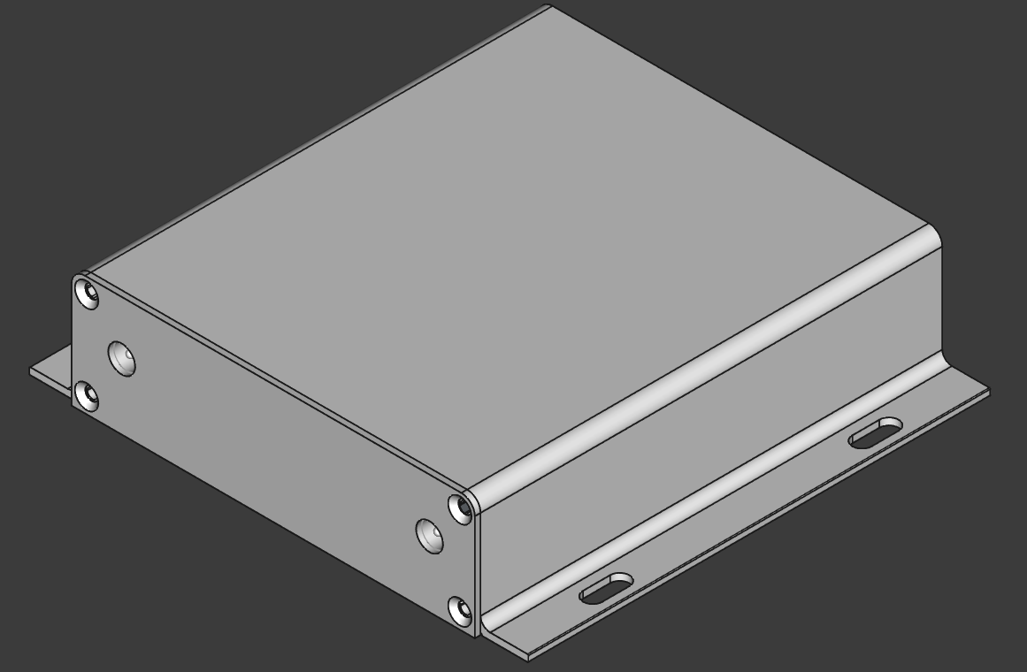
Compatible chassis:
BNC module:
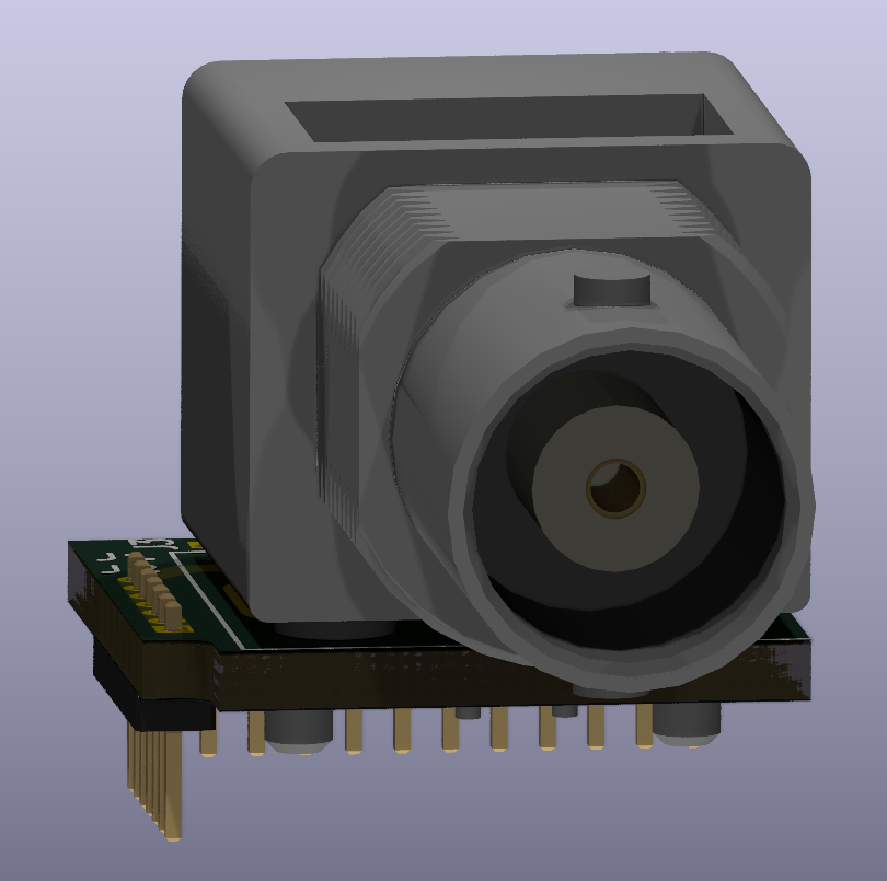
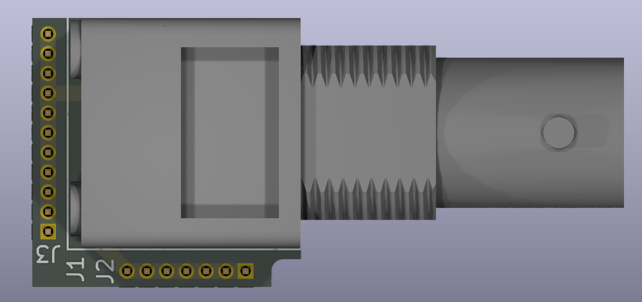
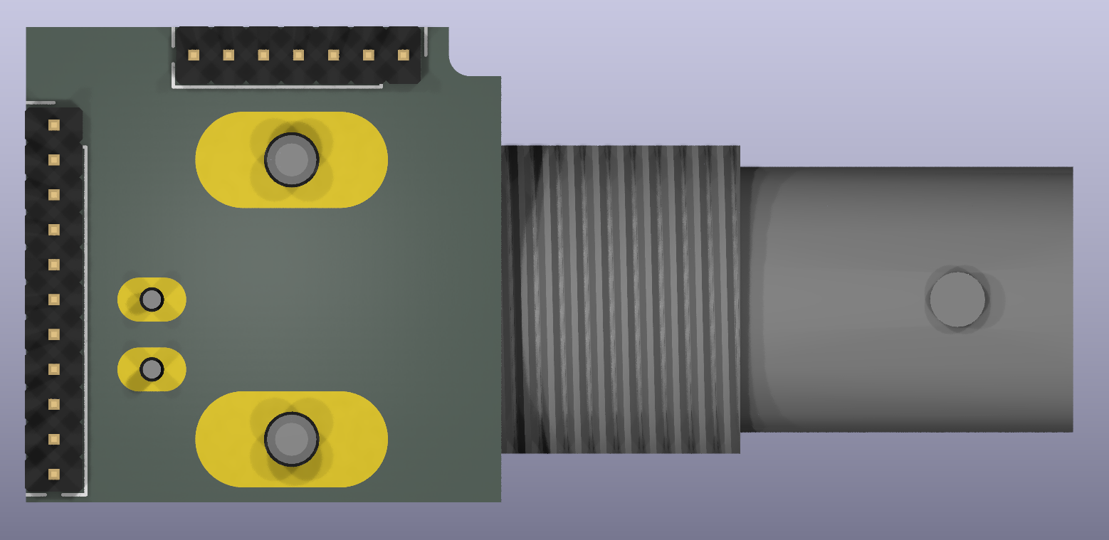
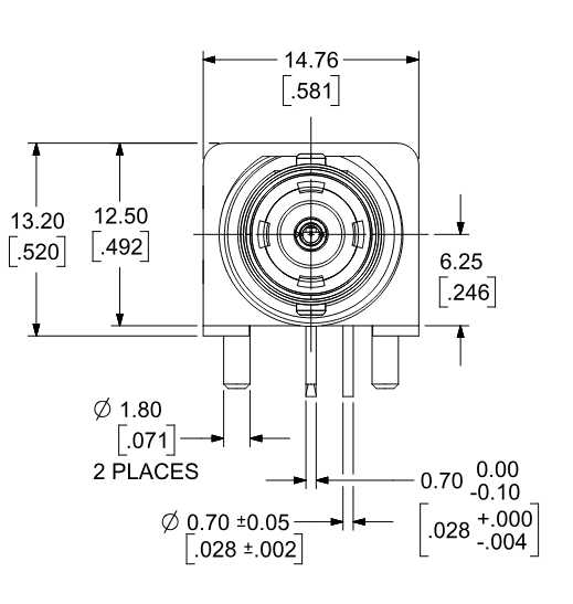
Note that BNC connector parts of this type may share the same footprint but differ in the height of the connector in order to vendor lock their customers. Check for the height of your part, which is 6.25mm in this example.
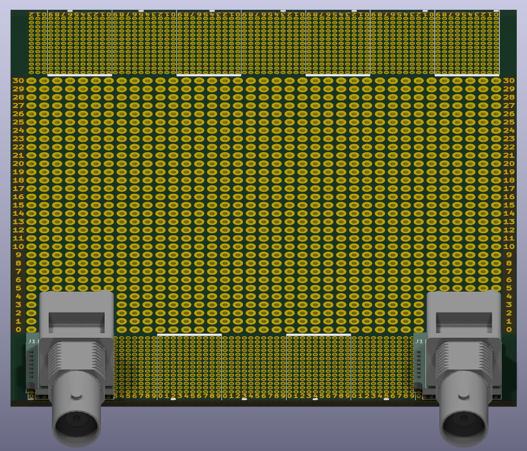
BNC reference design:
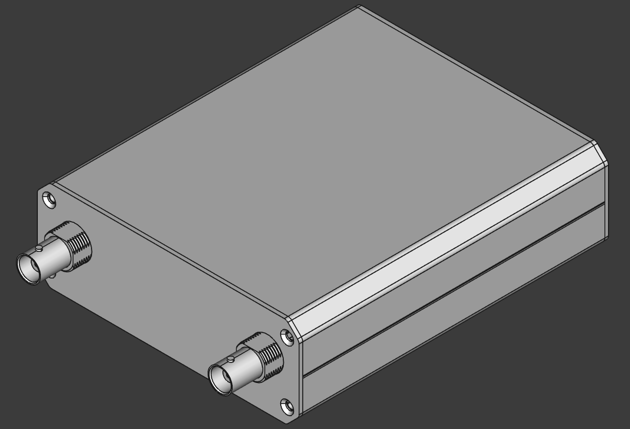
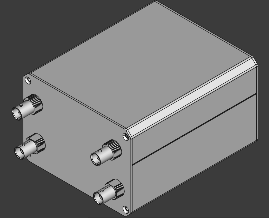
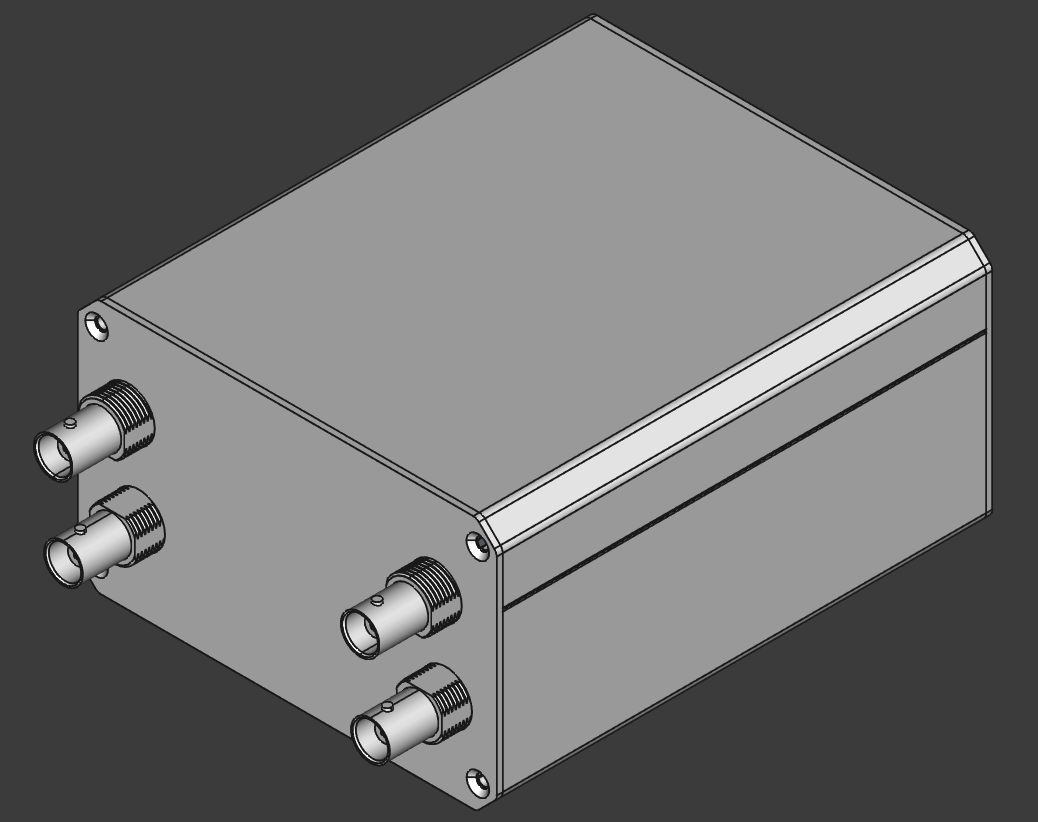
Barrel Jack module (PJ-063AH):
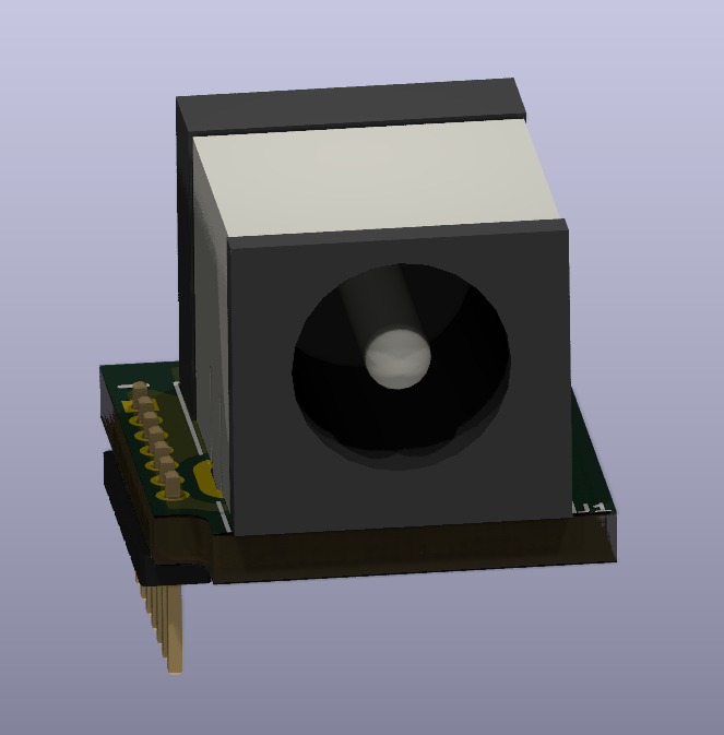
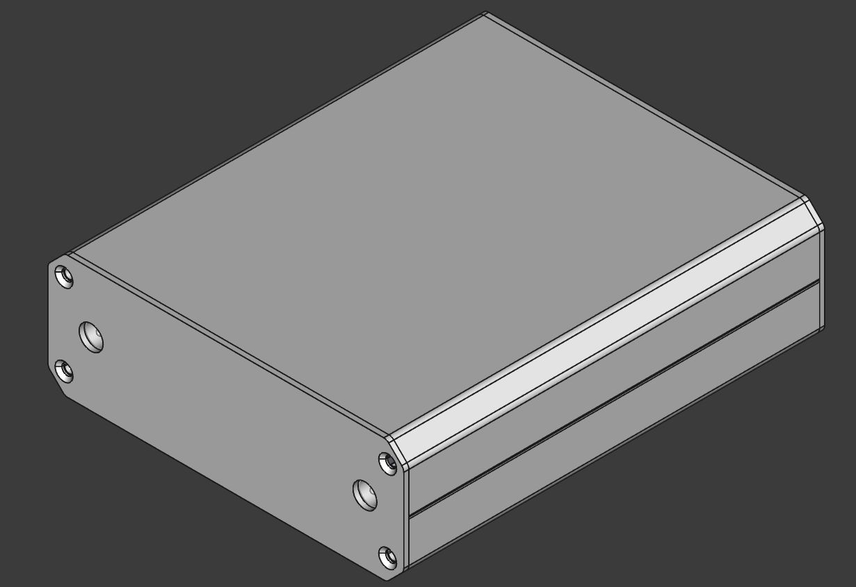
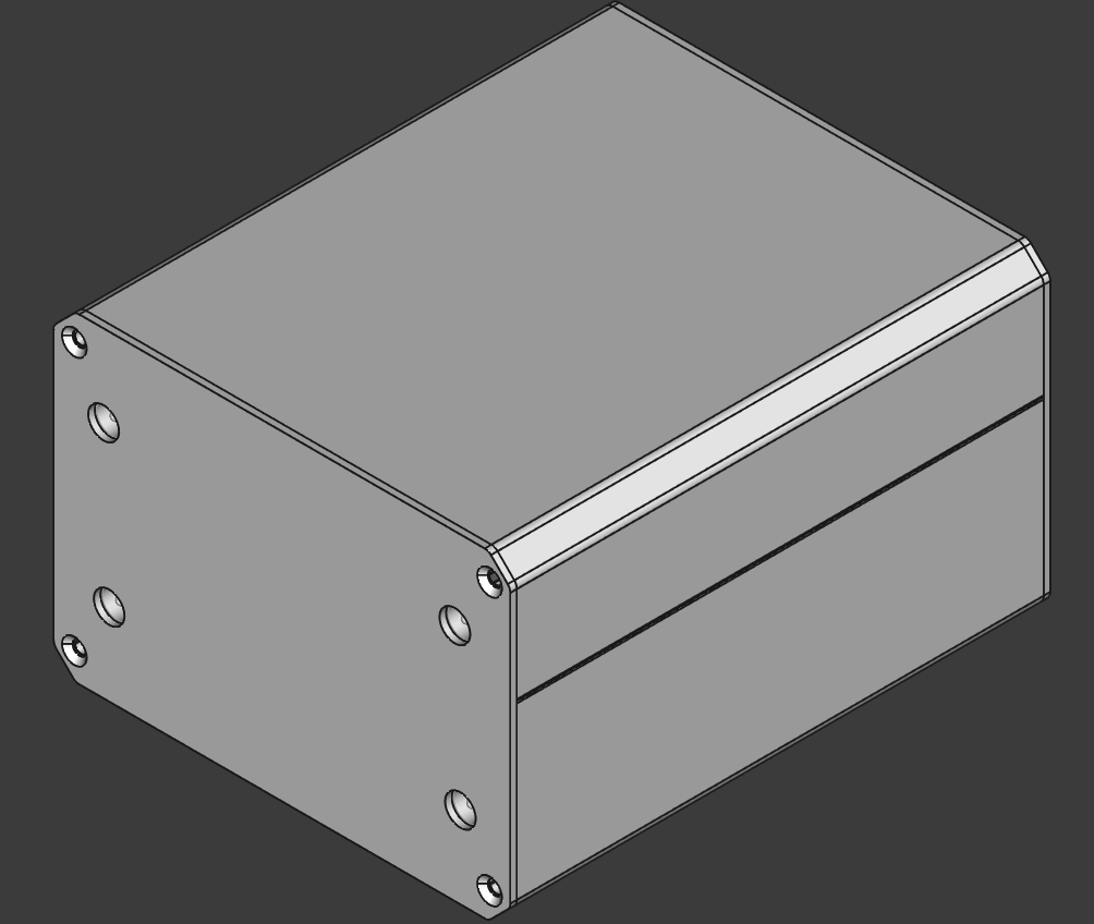
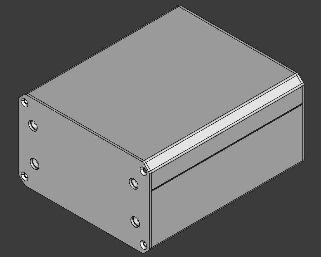
3.5mm Audio Jack module (SJ3-35083D-TR):
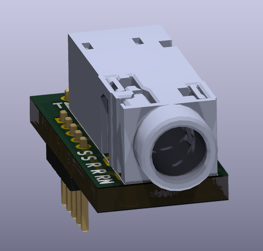
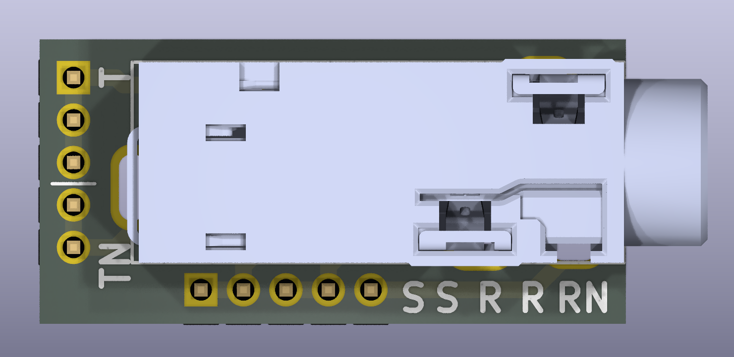
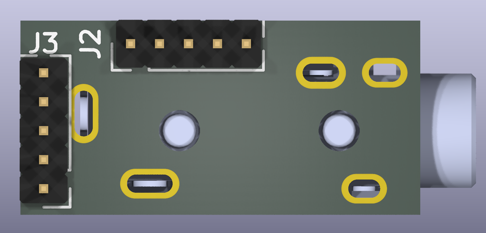
Audio jack reference design:
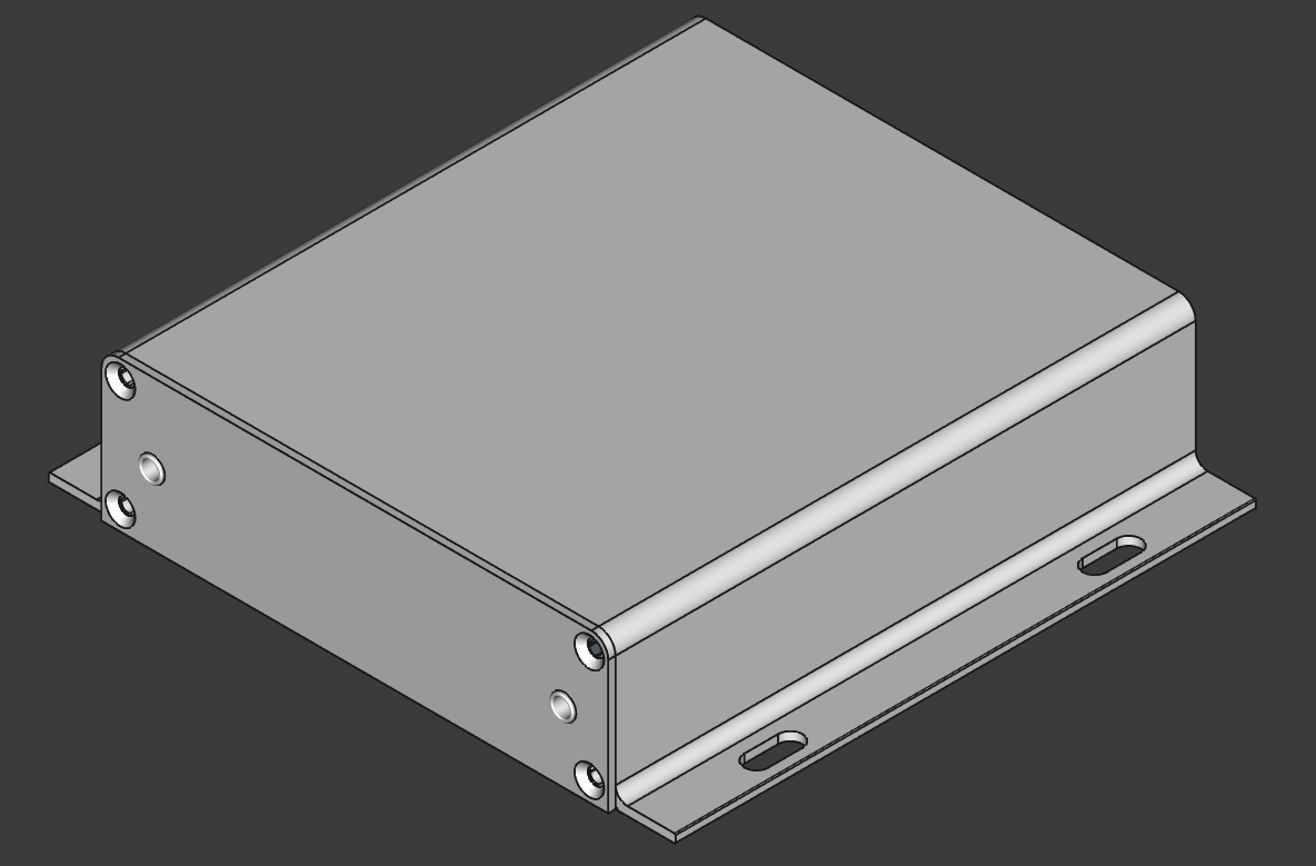
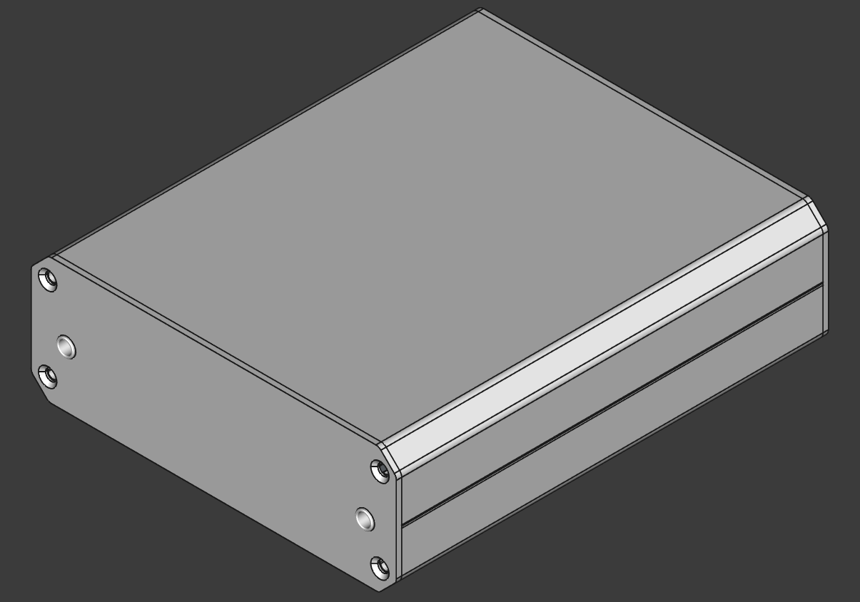
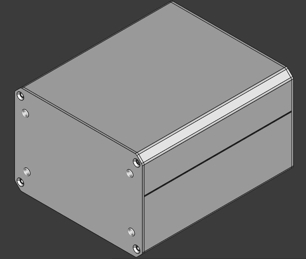
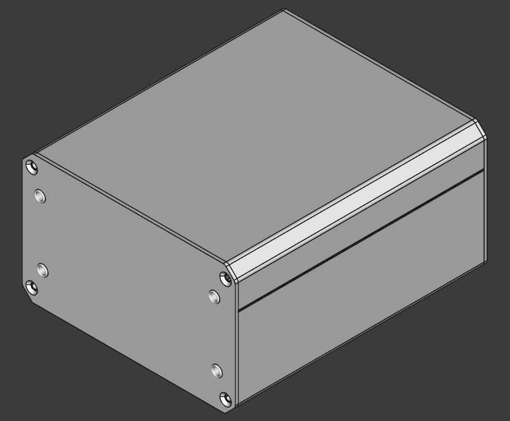
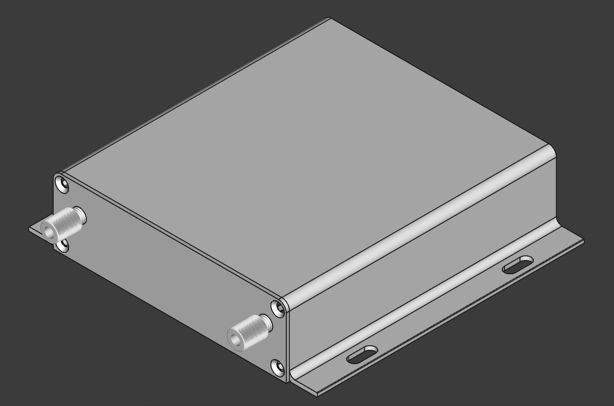
Chassis K127-13031-H7-L120:
4mm Banana Jack module (Banana_Cliff_FCR7350B_S16N-PC_Horizontal):
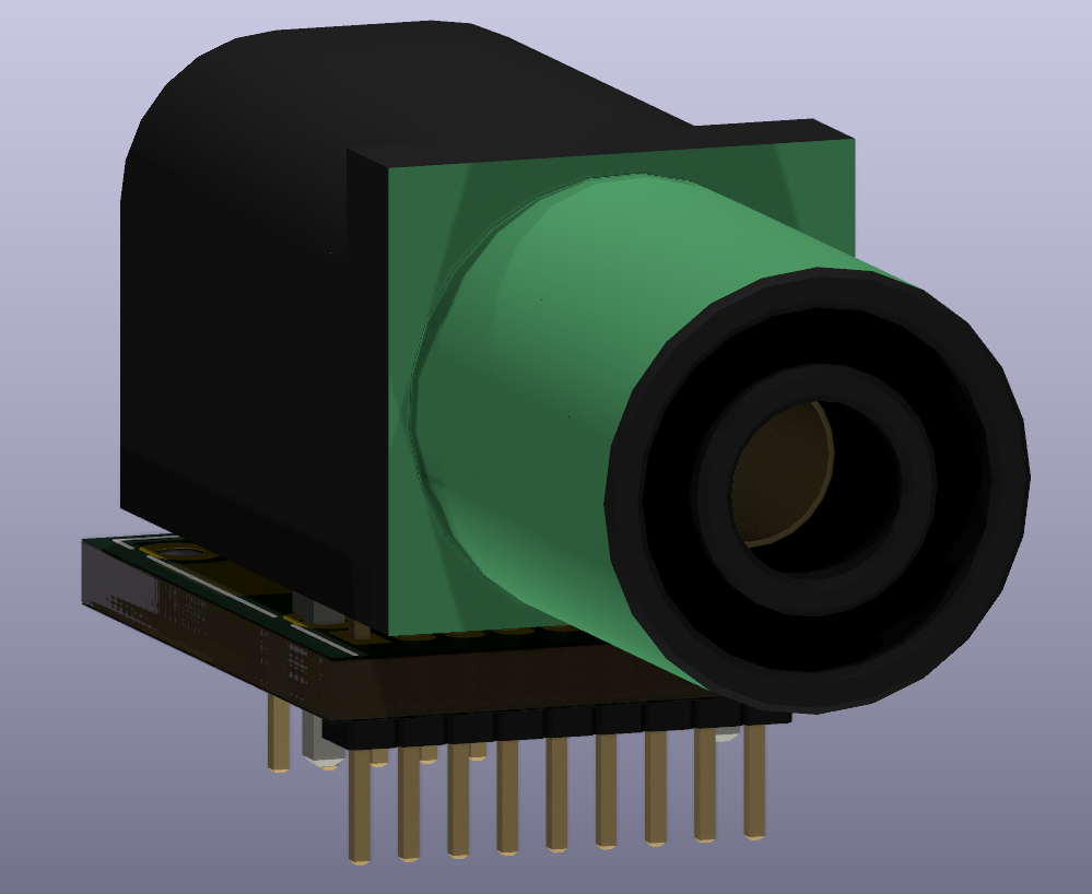
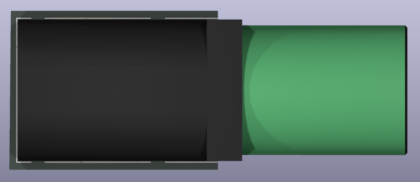
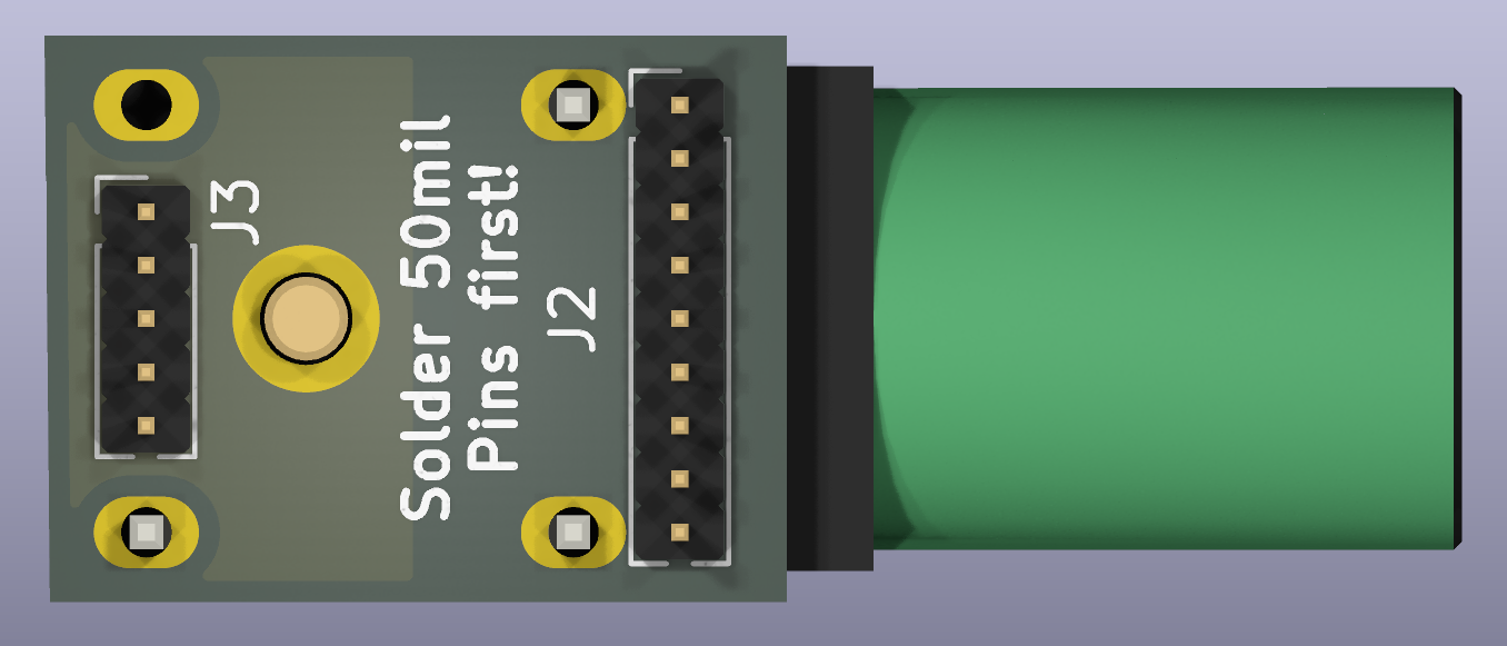
4mm Banana jack reference design:
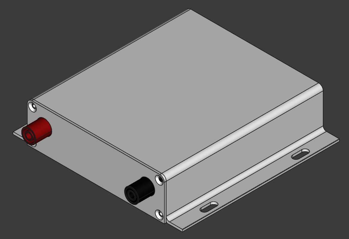
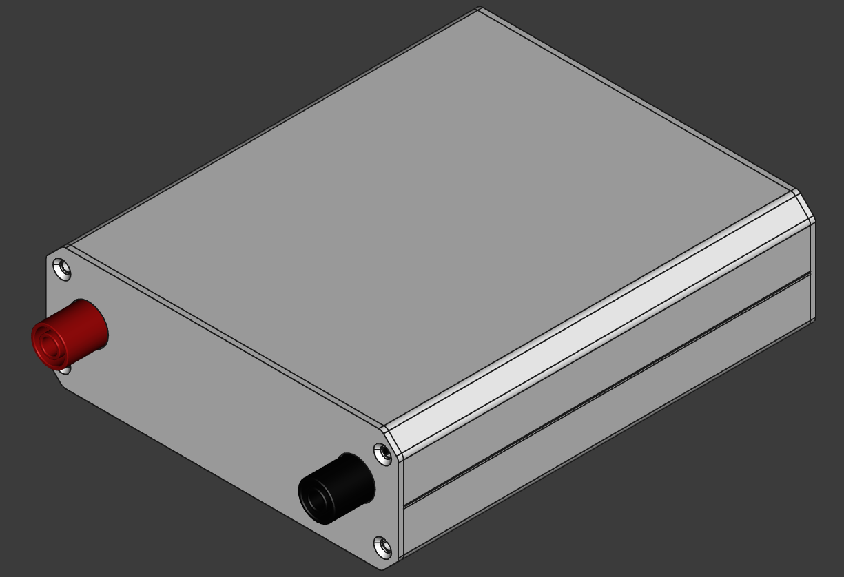
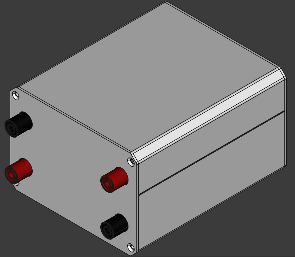
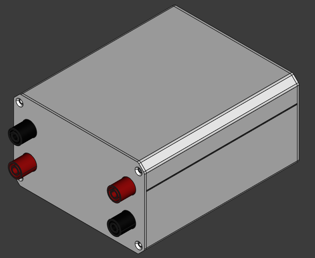
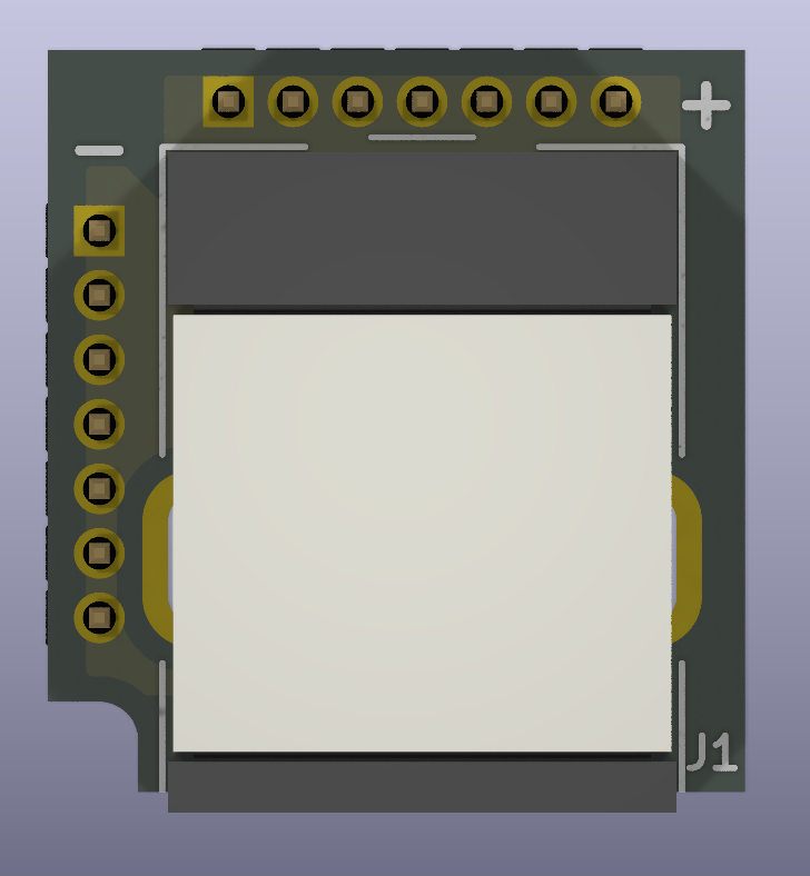
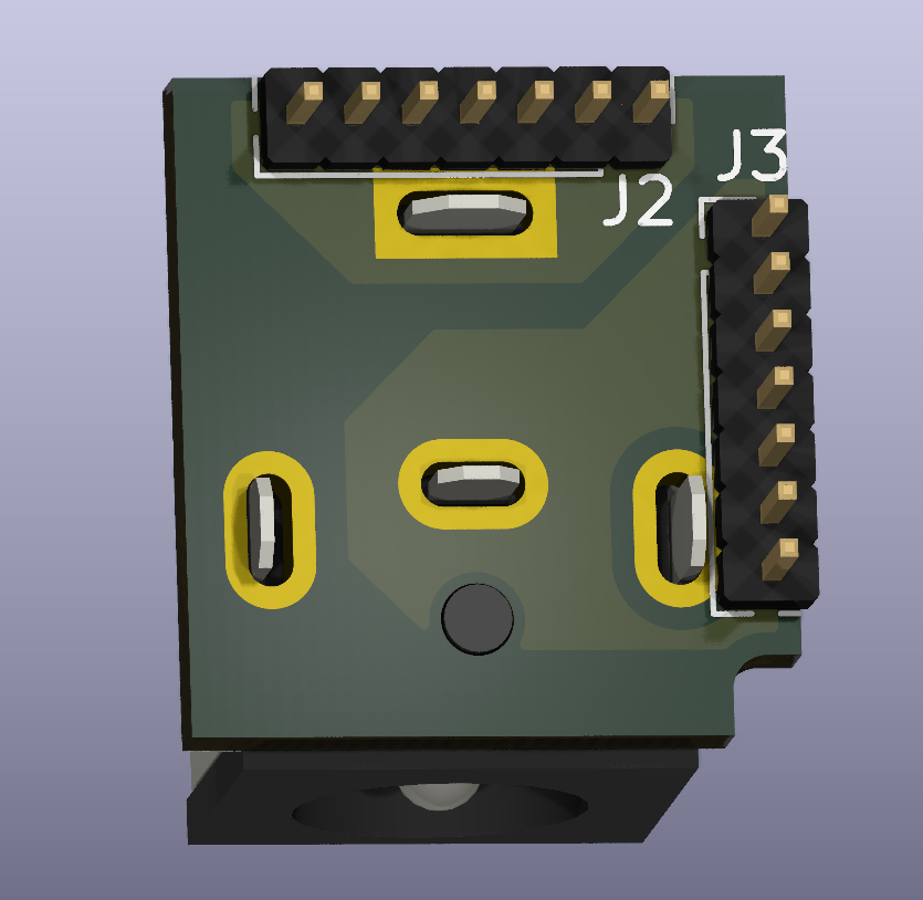
Connectorless PMMA plastic optic fiber receiver (IF-D91B):
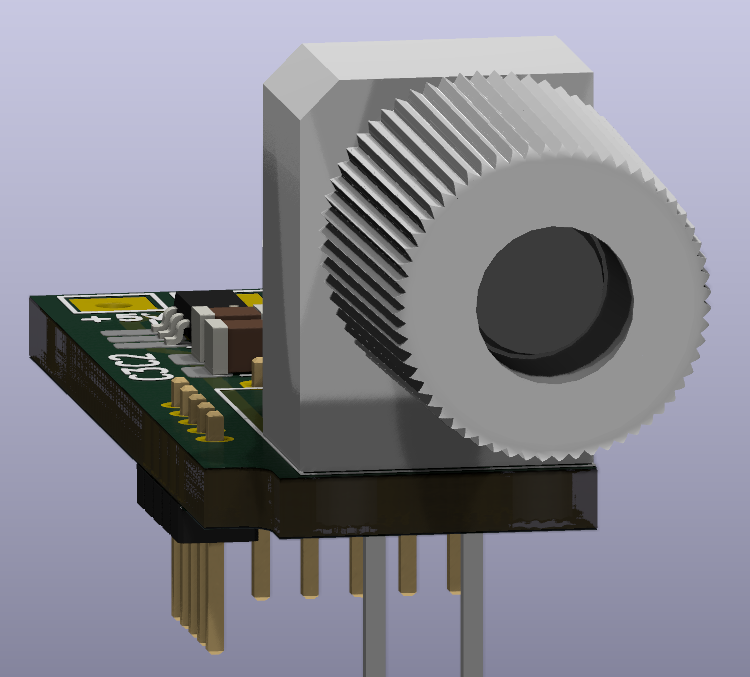
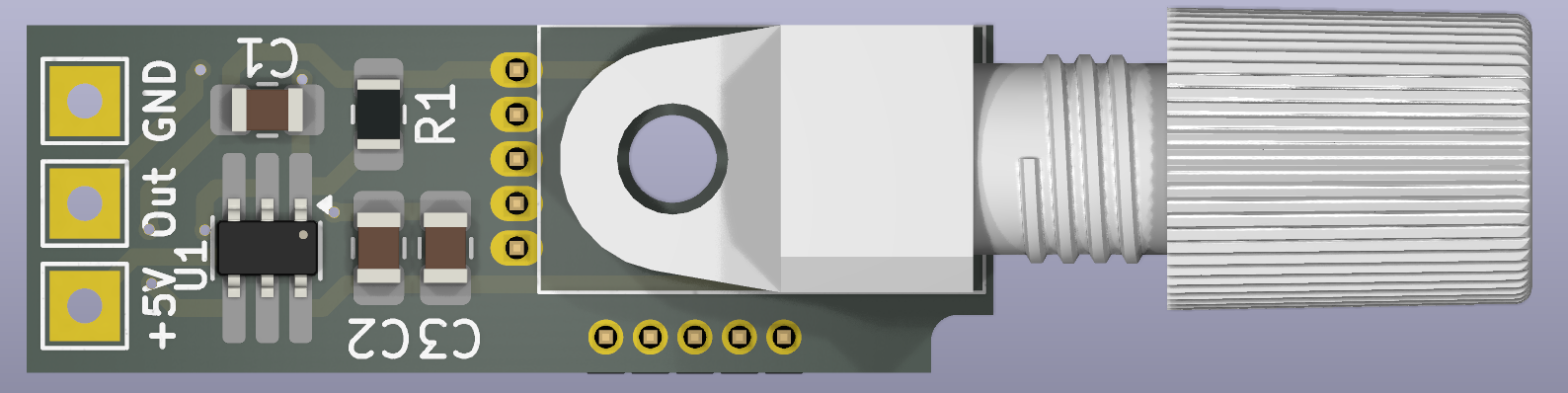
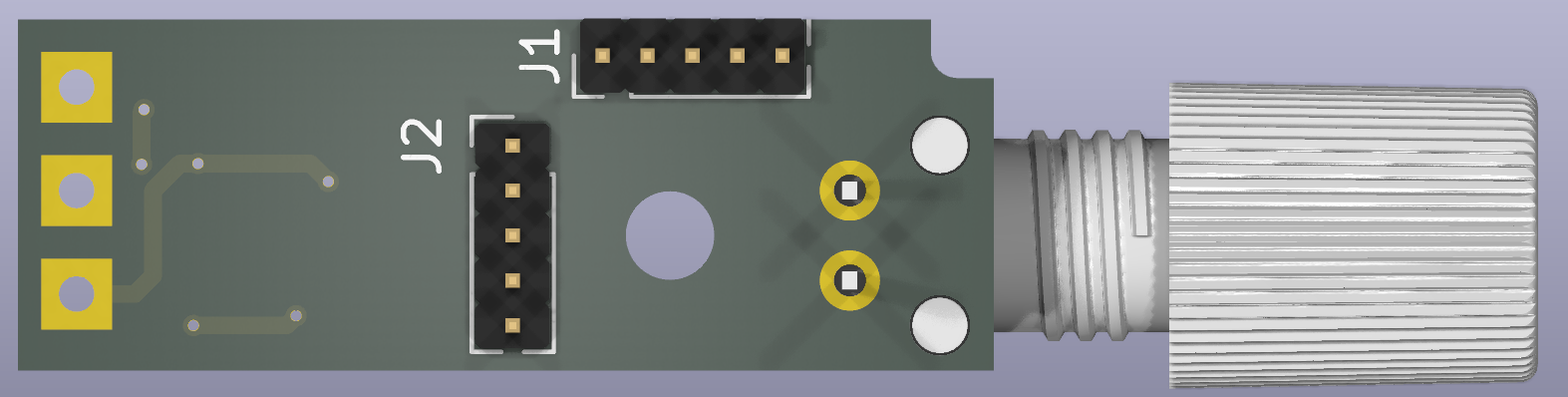
Connectorless PMMA plastic optic fiber receiver reference design:
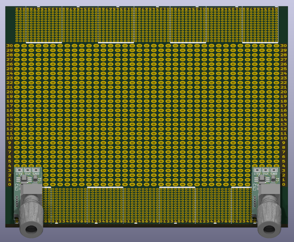
Chassis K127-13031-H7-L120:
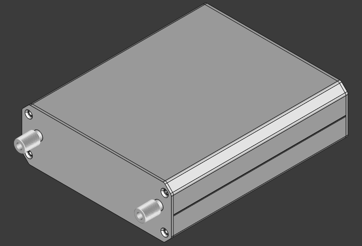
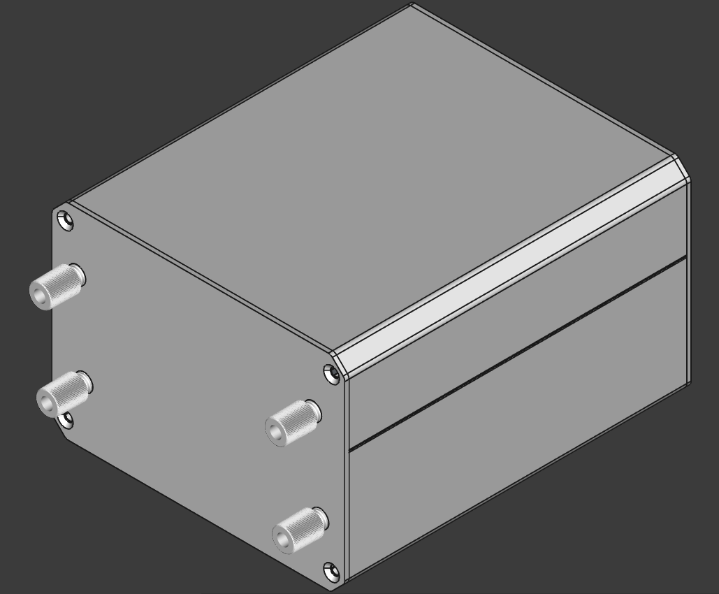
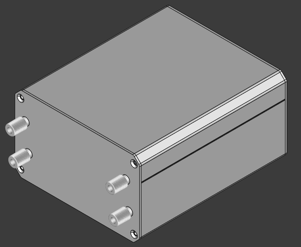
Connectorless PMMA plastic optic fiber transmitter (IF-E96E):
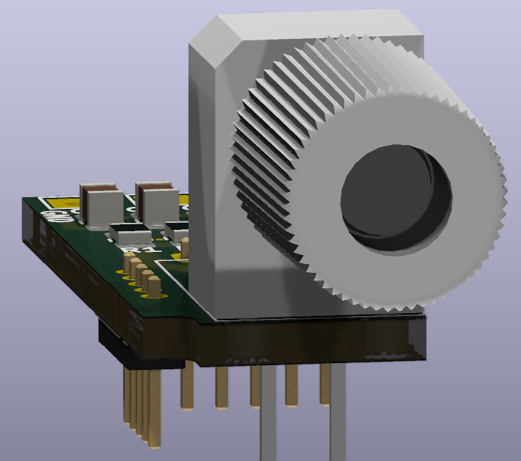
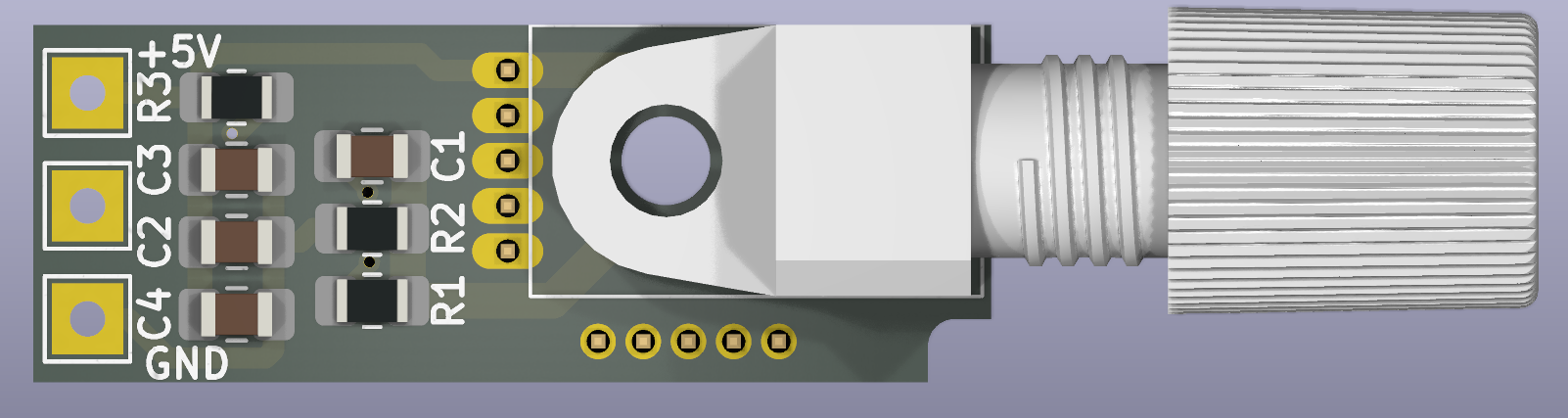
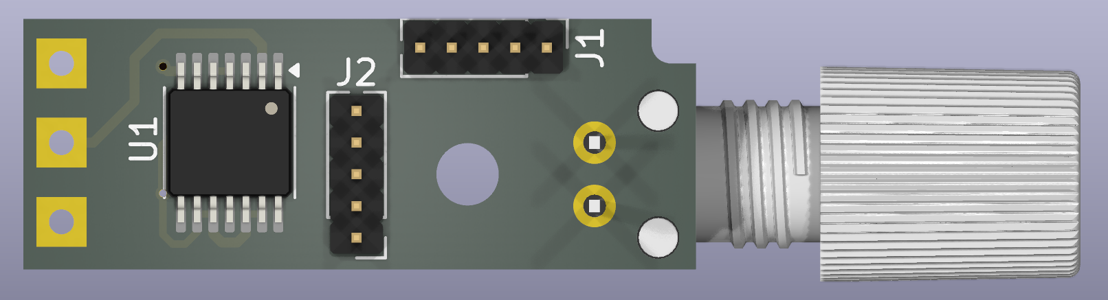
Connectorless PMMA plastic optic fiber transmitter reference design:
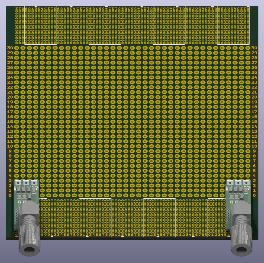
Chassis K127-13031-H7-L120:
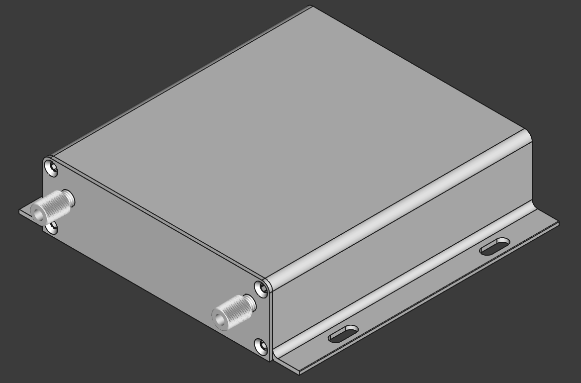
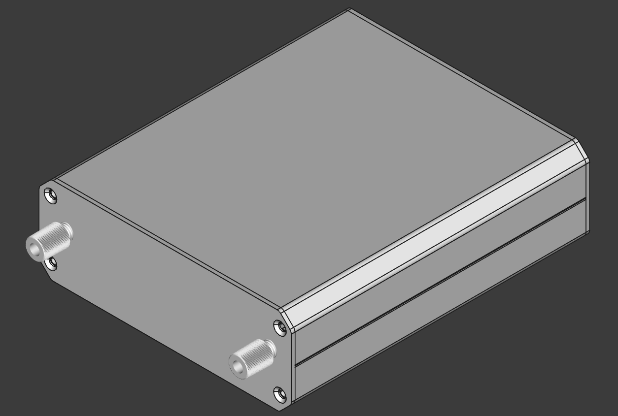
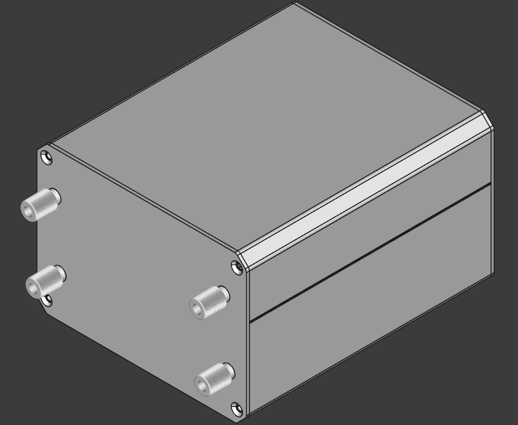
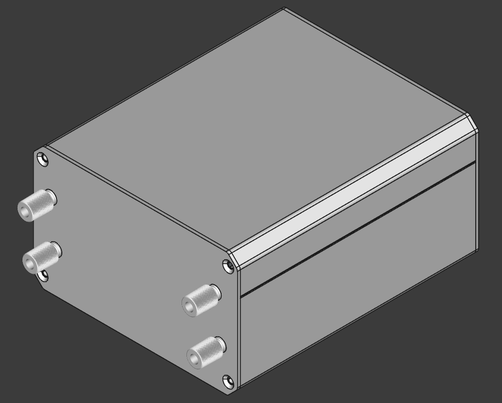
Right-angle tactile switch (PTS645V):
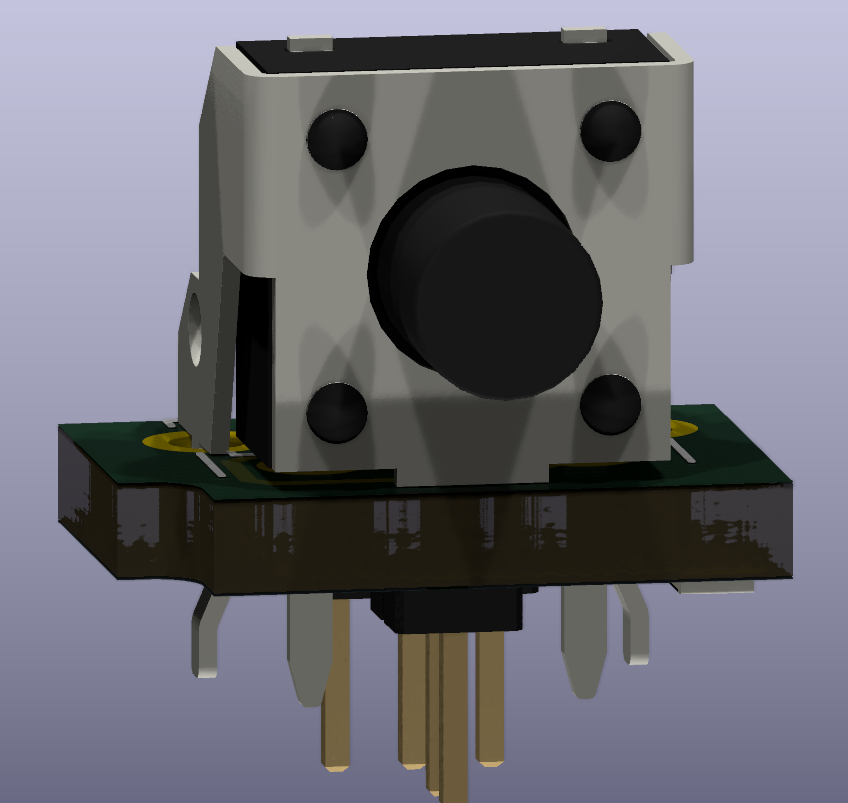
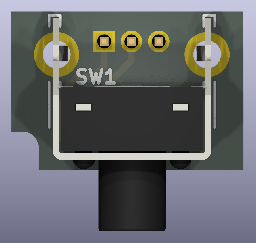
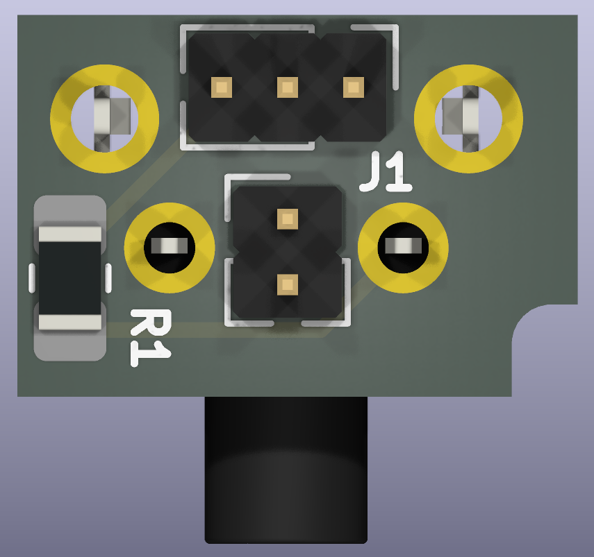
Right-angle tactile switch reference design:
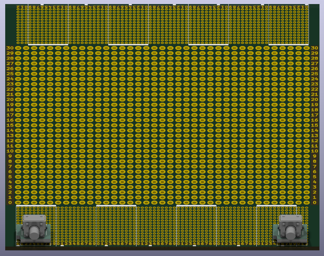
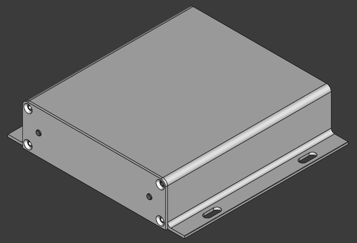
Chassis K127-13031-H7-L120:
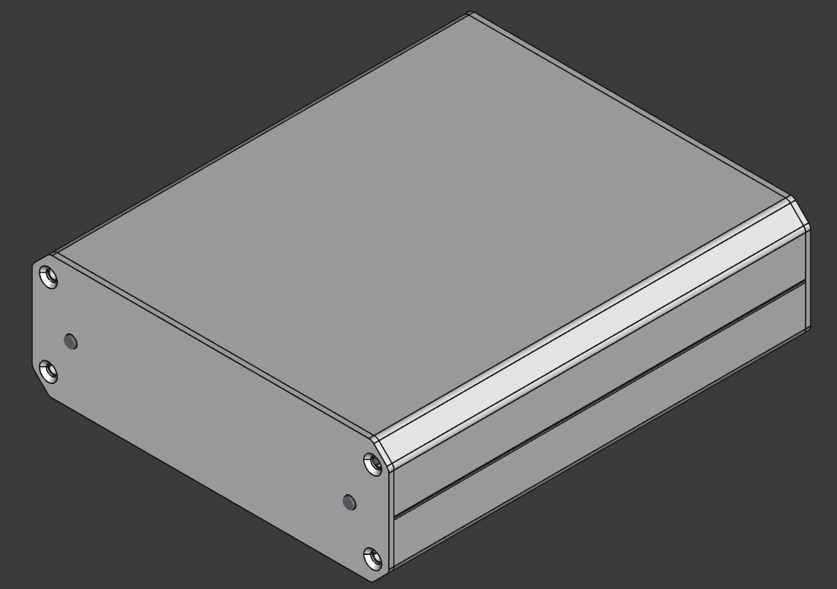
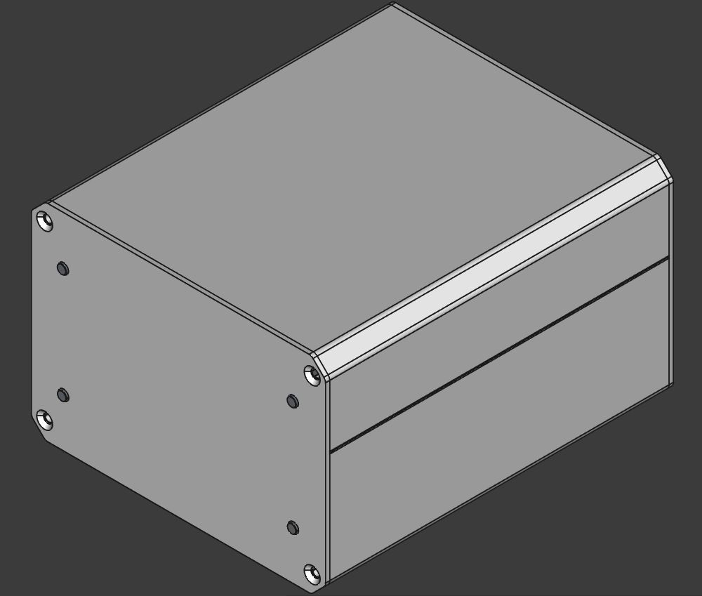
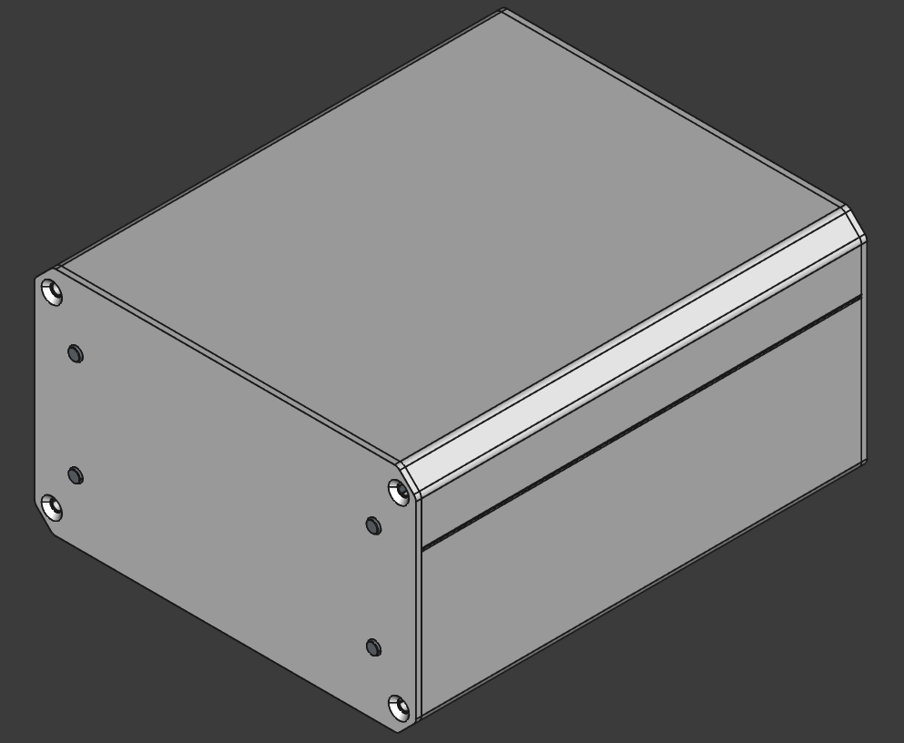
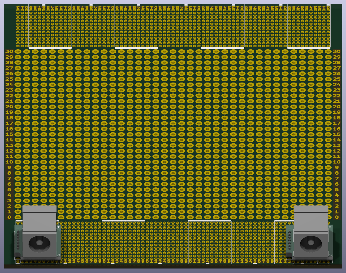
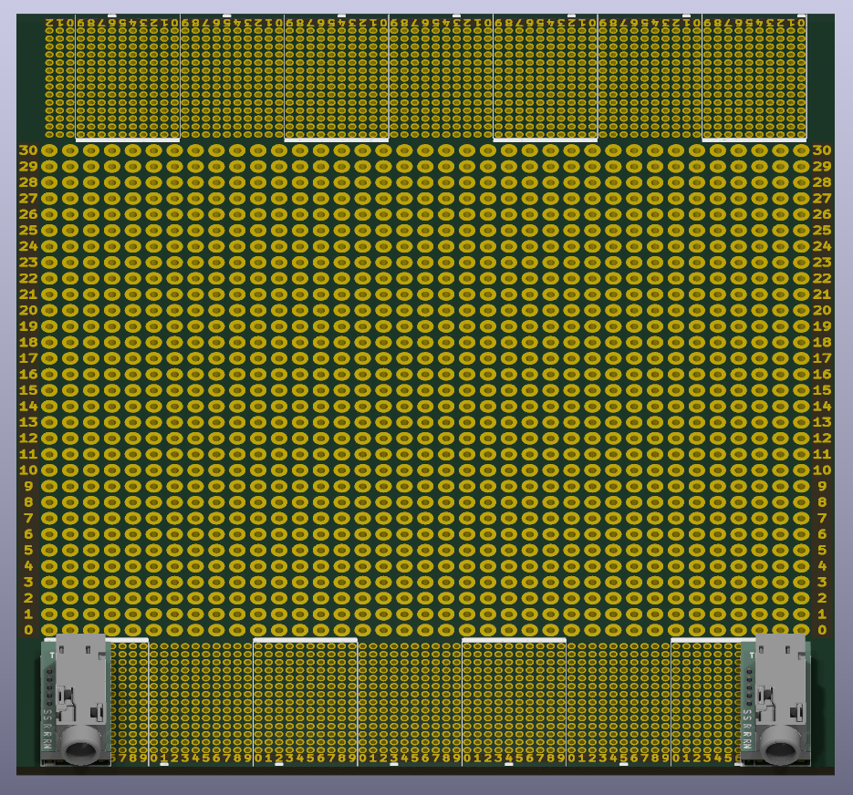
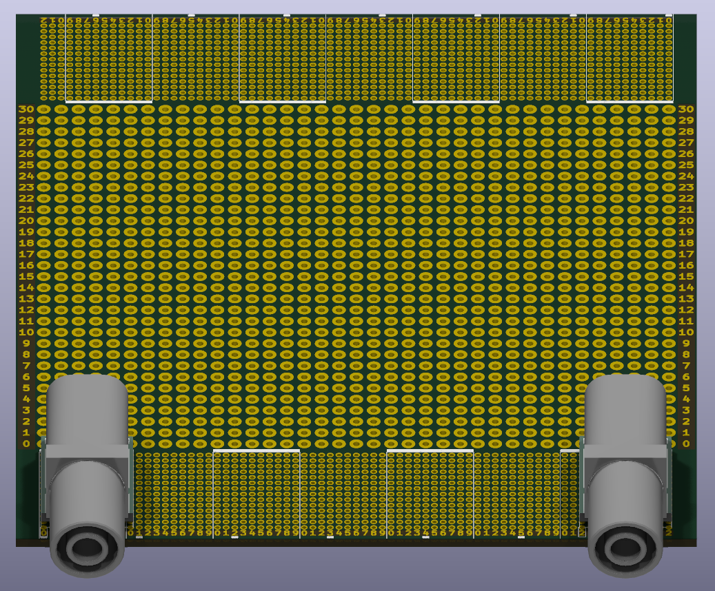
The indices of the modules used to determine the position of the modules on the protoboard:
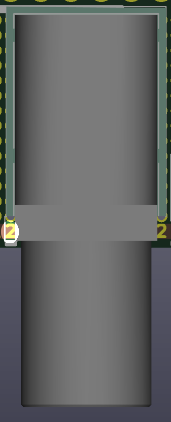
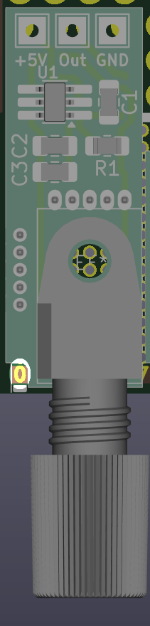
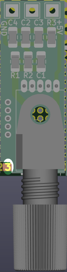
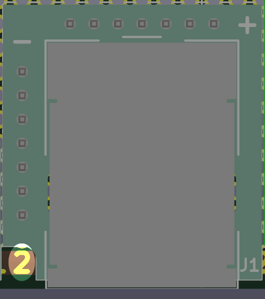
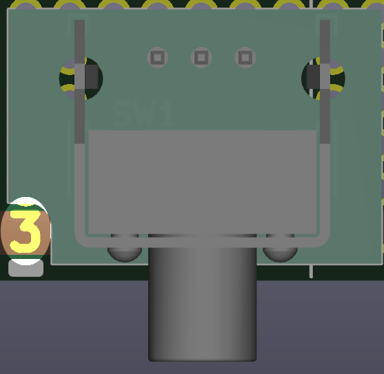
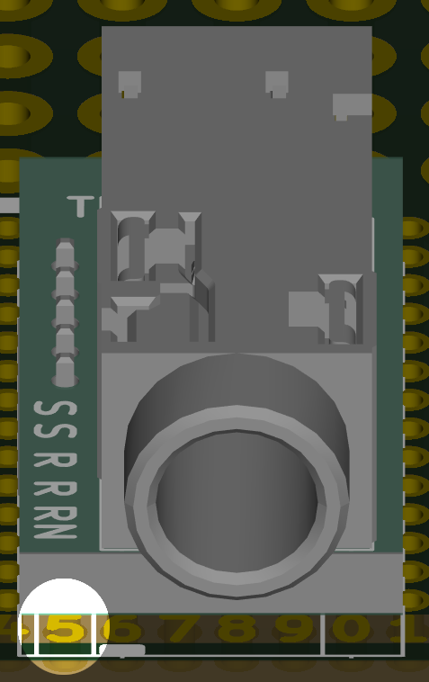
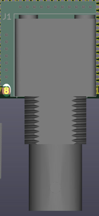
The white bars at the bottom edge of the protoboard mark the decadal numbers and the index has a range of 0..72.
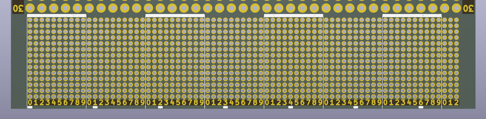
The following table lists the reference coordinates for the frontpanel hole if the module is sitting on the reference point (index == 0). The coordinates of the respective frontpanel hole can be calculated by adding (if the protoboard is component side up) or subtracting (if the protoboard is component side down) 1.27mm times index (of the module), since the modules are on a 50mil(1.27mm) grid.
I may write a FreeCAD script at some point to automate the generation of the frontpanel MCAD files.
| Chassis | Cutout Coordinates [X/Y] mm 4mm Banana D=11.5mm | Cutout Coordinates [X/Y] mm BNC D=13mm | Cutout Coordinates [X/Y] mm IF-D91B D=6.3mm | Cutout Coordinates [X/Y] mm IF-E96E D=6.3mm | Cutout Coordinates [X/Y] mm PJ-063AH D=7mm | Cutout Coordinates [X/Y] mm PTS645V D=3.6mm | Cutout Coordinates [X/Y] mm SJ3-35083D-TR D=5.2mm |
|---|---|---|---|---|---|---|---|
| K93-10436-H7-L120, level1, up | 12.63+index*1.27 / 19.92 | 15.18+index*1.27 / 20.72 | 11.36+index*1.27 / 20.6 | 11.36+index*1.27 / 20.6 | 12.63+index*1.27 / 18.62 | 11.38+index*1.27 / 17.12 | 10.09+index*1.27 / 16.15 |
| K127-13031-H7-L120, level1, up | 13.03+index*1.27 / 18.33 | 15.55+index*1.27 / 19.14 | 11.76+index*1.27 / 19.02 | 11.76+index*1.27 / 19.02 | 13.03+index*1.27 / 17.02 | 11.79+index*1.27 / 15.53 | 10.49+index*1.27 / 14.56 |
| K97-10473-H7-L120, level1, up | 12.63+index*1.27 / 19.92 | 15.17+index*1.27 / 20.70 | 11.36+index*1.27 / 20.64 | 11.36+index*1.27 / 20.64 | 12.63+index*1.27 / 18.62 | 11.38+index*1.27 / 17.12 | 10.09+index*1.27 / 16.15 |
| K97-10473-H7-L120, level4, down | 91.37-index*1.27 / 53.06 | 88.83-index*1.27 / 52.25 | 92.64-index*1.27 / 52.41 | 92.64-index*1.27 / 52.41 | 91.37-index*1.27 / 54.36 | 92.62-index*1.27 / 55.86 | 93.91-index*1.27 / 56.83 |
| K96-10463-H7-L120, level1, up | 12.63+index*1.27 / 19.93 | 15.17+index*1.27 / 20.74 | 11.36+index*1.27 / 20.58 | 11.36+index*1.27 / 20.58 | 12.63+index*1.27 / 18.63 | 11.38+index*1.27 / 17.14 | 10.09+index*1.27 / 16.16 |
| K96-10463-H7-L120, level4, down | 91.37-index*1.27 / 43.07 | 88.83-index*1.27 / 42.26 | 92.64-index*1.27 / 42.35 | 92.64-index*1.27 / 42.35 | 91.37-index*1.27 / 44.38 | 92.62-index*1.27 / 45.88 | 93.91-index*1.27 / 46.84 |
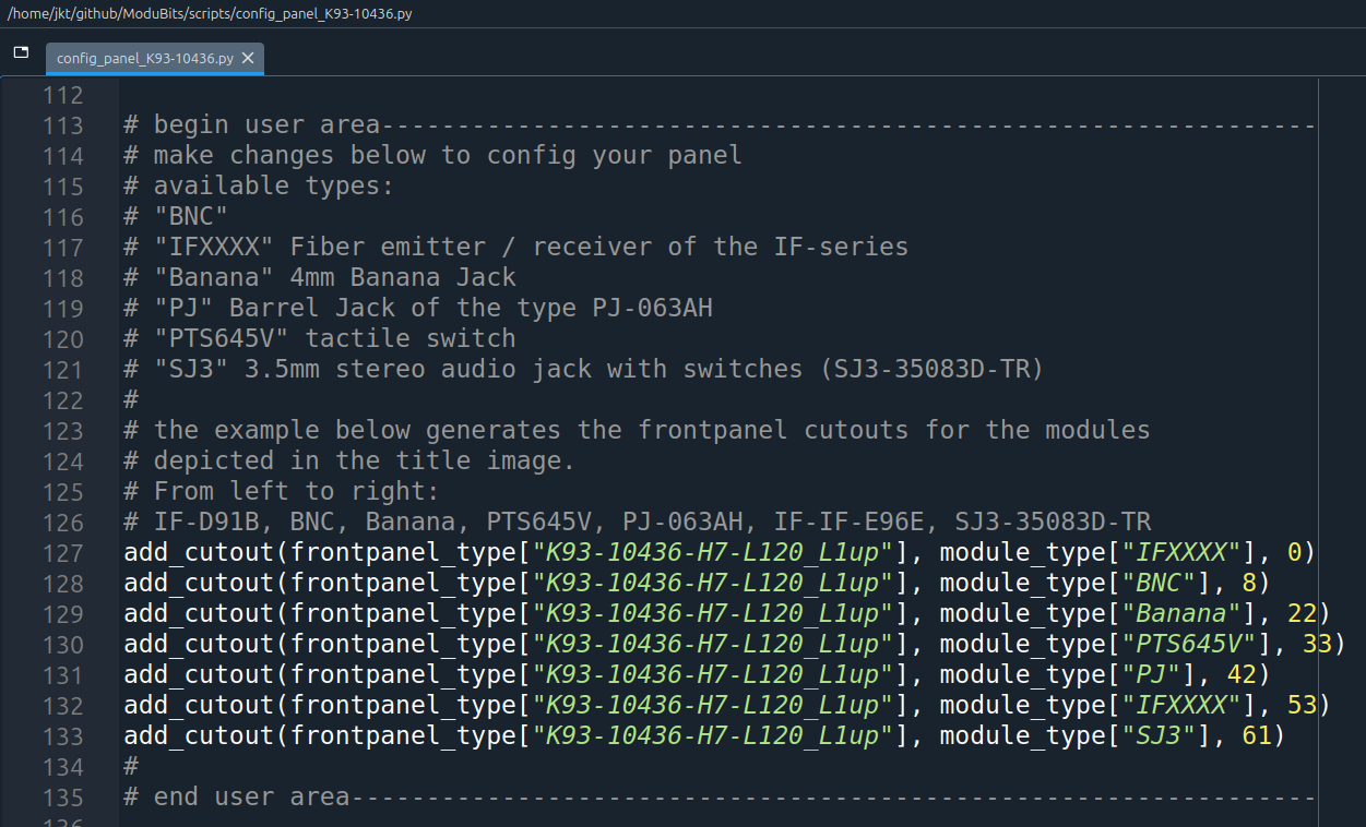
Following frontpanel was generated by opening "K93-10436-H7-L120_frontpanel_blank.FCStd" and plopping the python script "config_panel_K93-10436.py" into the Python console of FreeCAD. This script is hard-coded and ugly, yes, I'm acutely aware but it's also easy to read / understand and I'm not a coder. :3
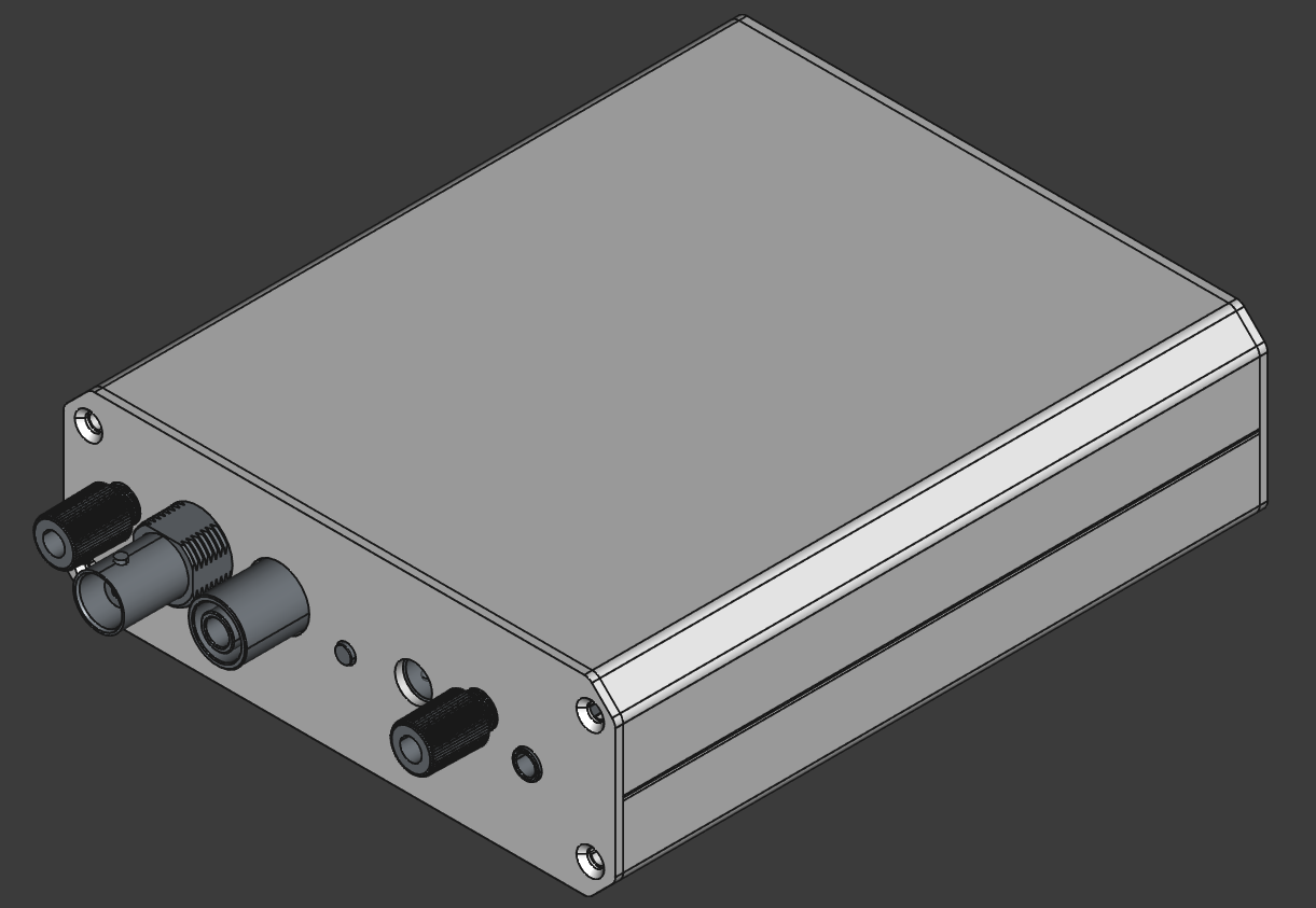
The following image depicts the user area of the generator script that configures the frontpanel modifications.
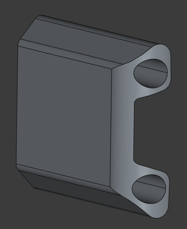
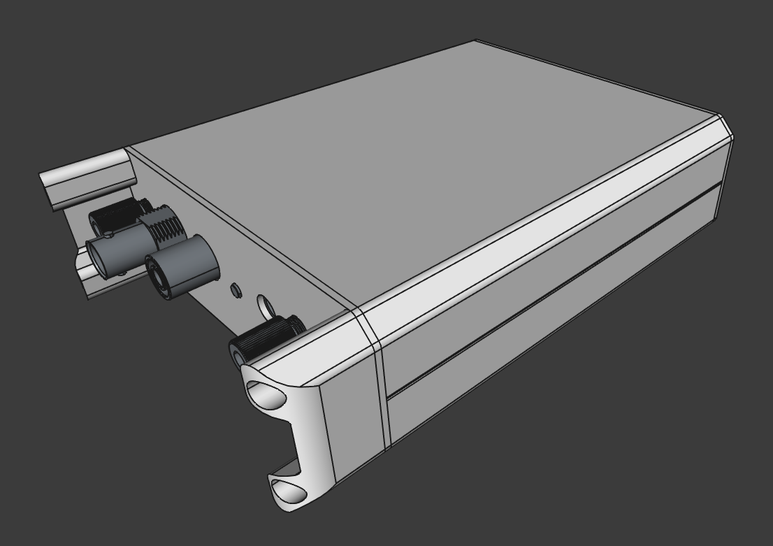
I don't like my connectors getting mangled or smushed, so I designed a simple sacrificial part that will absorb the brunt of the impact force when the chassis is dropped or inadequately packaged. The part is attached to the chassis by using the M3 threads in the chassis, sandwiching the front panel between the chassis and the bumper part. I wanted to round the corners a bit further but I couldn't get the "fillet" tool to do its thing since the FreeCAD implementation is less forgiving than the equivalent tool in commercial MCAD tools.
The Tarantinorino is a corner piece with rubbery feet on all relevant sides to allow these chassis to either be used stacked like a tower or standing on the desk as an instrument centipede.
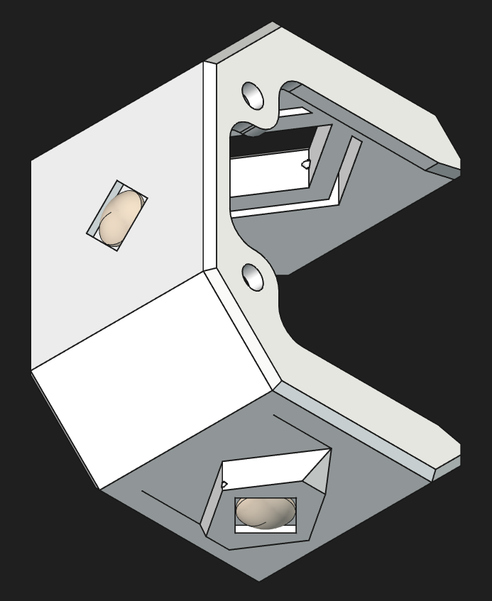
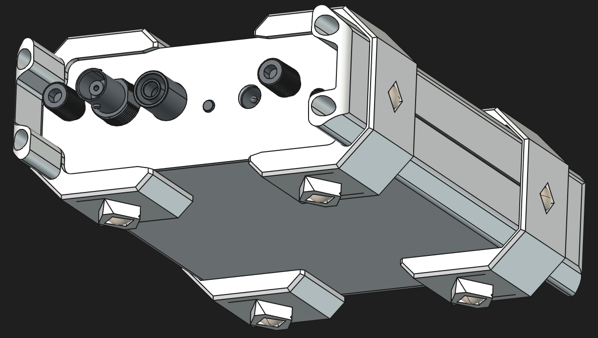
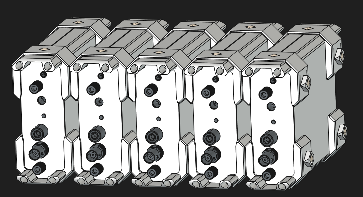
Same as above but with the improved DockLink-Frame:
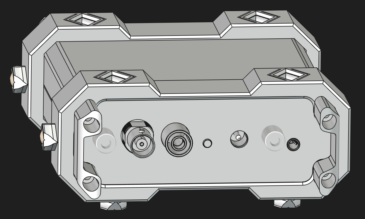
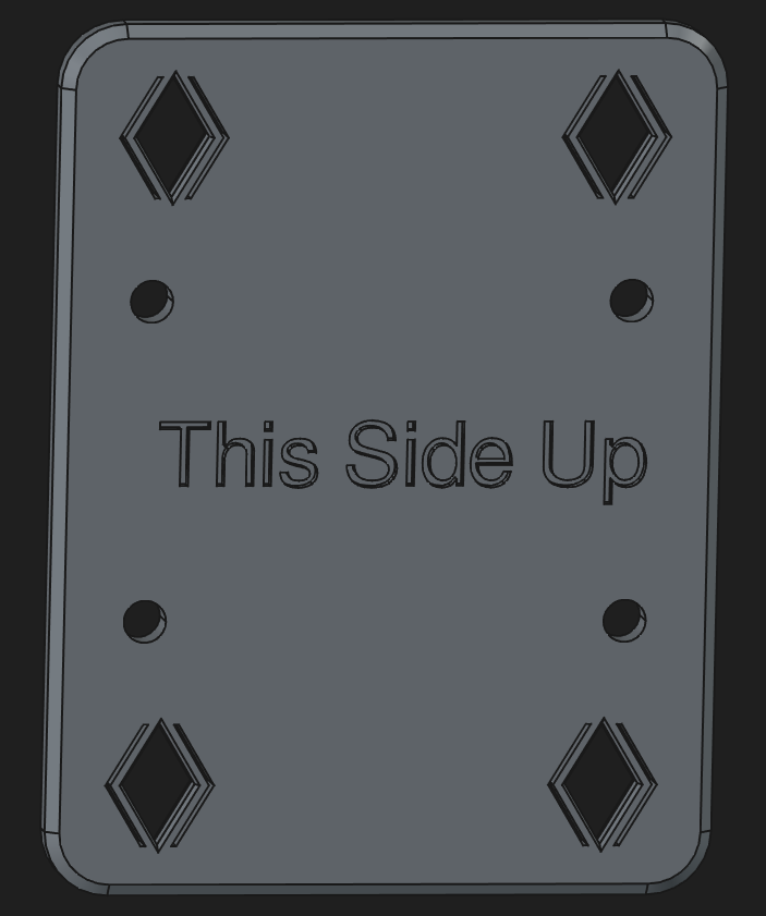
Here's a short video showing off the DockLink-Base-plate with two attached chassis: DockLink-Base-plate
| Qty | Value | Footprint | References |
|---|---|---|---|
| 2 | 100n | Capacitor_SMD:C_0805_2012Metric_Pad1.18x1.45mm_HandSolder | C3, C4 |
| 2 | Conn_01x05_Pin | Connector_PinHeader_1.27mm:PinHeader_1x05_P1.27mm_Vertical | J1, J2 |
| 1 | +5V | TestPoint:TestPoint_THTPad_2.0x2.0mm_Drill1.0mm | TP1 |
| 1 | 10k | Resistor_SMD:R_0805_2012Metric_Pad1.20x1.40mm_HandSolder | R3 |
| 1 | 10u | Capacitor_SMD:C_0805_2012Metric_Pad1.18x1.45mm_HandSolder | C2 |
| 1 | 15p | Capacitor_SMD:C_0805_2012Metric_Pad1.18x1.45mm_HandSolder | C1 |
| 1 | 200R | Resistor_SMD:R_0805_2012Metric_Pad1.20x1.40mm_HandSolder | R1 |
| 1 | 560R | Resistor_SMD:R_0805_2012Metric_Pad1.20x1.40mm_HandSolder | R2 |
| 1 | GND | TestPoint:TestPoint_THTPad_2.0x2.0mm_Drill1.0mm | TP3 |
| 1 | IF E96E | IF-E96E:IF-E96E | D1 |
| 1 | SN74ACT08PWR | Package_SO:TSSOP-14_4.4x5mm_P0.65mm | U1 |
| 1 | ~{Input} | TestPoint:TestPoint_THTPad_2.0x2.0mm_Drill1.0mm | TP2 |
JKTsDoodles/ModuBits
This is a versatile set of prototyping boards and modules designed to fit chassis measuring 100mm wide and 120mm deep.

JKTsDoodles/ModuBits
This is a versatile set of prototyping boards and modules designed to fit chassis measuring 100mm wide and 120mm deep.

JKTsDoodles/ModuBits
This is a versatile set of prototyping boards and modules designed to fit chassis measuring 100mm wide and 120mm deep.

JKTsDoodles/ModuBits
This is a versatile set of prototyping boards and modules designed to fit chassis measuring 100mm wide and 120mm deep.

JKTsDoodles/ModuBits
This is a versatile set of prototyping boards and modules designed to fit chassis measuring 100mm wide and 120mm deep.

JKTsDoodles/ModuBits
This is a versatile set of prototyping boards and modules designed to fit chassis measuring 100mm wide and 120mm deep.

google/mozc-devices
Circuit diagrams and firmware source code for Gboard DIY keyboards


hackclub/OnBoard
💡 Join 1,000 teenagers and make your first PCB with a $100 grant!


Twotoz/C5VRX
Ultra-minimal, zero-CPU 5.8 GHz analog FPV video receiver using ESP32-C5 Wi-Fi 6 PHY MODEM_DIAG, BitScrambler WBFM demodulation & resistor DAC CVBS


It measures 10 × 26.9 mm and has 2 copper layers, 1.6 mm thick.
14 parts. The full list of its parts is on this page, with links to each part's symbol and footprint where PCBKit's library has them.
From the JKTsDoodles/ModuBits repository on GitHub, at the commit this page was made from: the board is 50mil_IF-E96E_breakout/50mil_IF-E96E_breakout.kicad_pcb and its schematic 50mil_4mm_banana_jack_breakout/50mil_4mm_banana_jack_breakout.kicad_sch. PCBKit opens the board in the browser, with nothing to install.
Its repository publishes it under the MIT licence: you may reuse it on that licence's terms (keep the author's notice, and for a copyleft licence share your changes alike).