2 layers48.8 × 50.4 mm
 JAJV02002/PV-Monitoring-System
ESP32 firmware and PHP/MySQL web application for a bachelor’s thesis photovoltaic monitoring system.
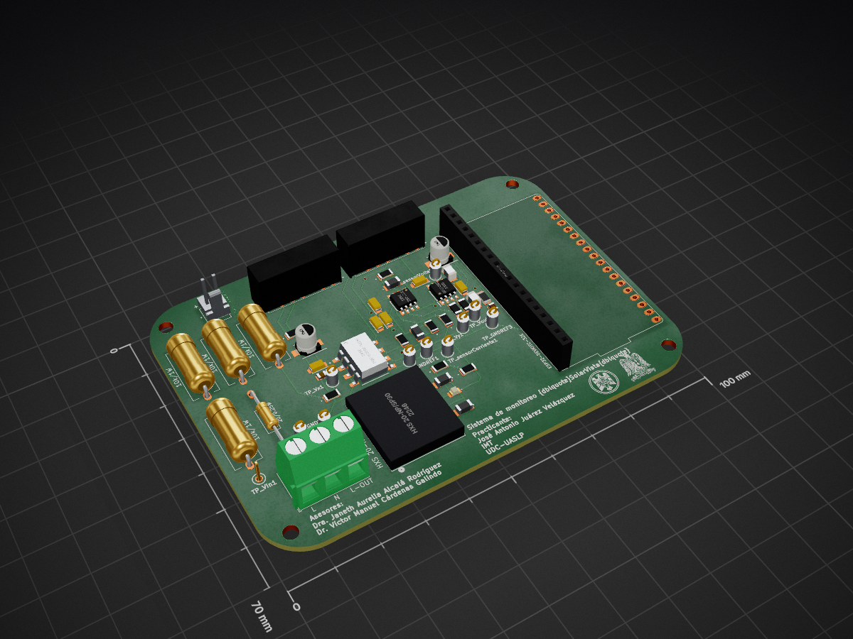
Monitoring board is an open-source printed circuit board by JAJV02002, from the JAJV02002/PV-Monitoring-System repository on GitHub. It is a 2-layer board of 100 × 70 mm with 59 parts on 71 nets, routed with 277 tracks and 11 vias.
It is built around the ESP32-DEVKITC-32E, RB-0505D and OP27GSZ, with the HCPL-7800A-300E among its other parts. Its parts include 19 resistors, 14 capacitors, 5 ICs and 2 diodes. It belongs with the ESP32 boards of this library.


Editable schematic, board layout and project-local component libraries for the monitoring unit.
| Directory | Contents |
|---|---|
| footprints.pretty | 19 custom footprints, including the two logos placed on the board |
| symbols | 7 custom symbol libraries referenced by the schematic |
| 3dmodels | 16 component STEP models referenced by the board |
The component selection follows the PCB component references and its design BOM, with the two board-logo footprints included because they are part of the layout. Unused parts, plugins, caches and backups are excluded. The purchasing BOM is EMON_BOM.xlsx.
monitoring-board.kicad_pro from this directory.${KIPRJMOD}; no personal library-folder path is required.Standard KiCad components remain linked to the installed libraries. The custom models in 3dmodels/ use project-relative paths. Keep this directory structure intact when copying the project.
| Qty | Value | Footprint | References |
|---|---|---|---|
| 11 | 5001 | footprints:test-point-5001 | TP_GND1, TP_GND2, TP_GNDREF1, TP_GNDREF2, TP_GNDREF3, TP_sensorCorriente1, TP_sensorVoltaje1, TP_Vin1, TP_Vout1, TP_Vx1, TP_Vy1 |
| 6 | 0.1uF/Tan | footprints:capacitor-TAJS104K020RNJ | C3, C4, C6, C8, C10, C11 |
| 4 | 10k/1W | Resistor_THT:R_Axial_DIN0614_L14.3mm_D5.7mm_P15.24mm_Horizontal | R1, R2, R3, R4 |
| 2 | 100k/0.25W | footprints:resistor-CR1206-FX-1003ELF | R15, R17 |
| 2 | 10uF/Elec | footprints:capacitor-EXV106M025A9BAA | C2, C9 |
| 2 | 1k/0.25W | footprints:resistor-RCC12061R00FKEA | R6, R19 |
| 2 | 200pF/Cer | footprints:capacitor-C1206C201F4HACTU | C5, C7 |
| 2 | 22k/0.25W | footprints:resistor-RCC12061R00FKEA | R10, R11 |
| 2 | 330/0.25W | Resistor_SMD:R_1206_3216Metric | R_Led1, R_Led2 |
| 2 | 33nF/Cer | footprints:capacitor-C1206C201F4HACTU | C12, C14 |
| 2 | 39k/0.25W | footprints:resistor-RCC12061R00FKEA | R8, R9 |
| 2 | 82k/0.25W | footprints:resistor-CRGH1206J82K | R12, R16 |
| 2 | OP27GSZ | footprints:OP27GSZ | IC2, IC3 |
| 2 | RB-0505D | footprints:RB-0505D | PS_HV1, PS_LV1 |
| 2 | RED_LED | LED_SMD:LED_1206_3216Metric | D1, D2 |
| 1 | 1.2k/0.25W | footprints:resistor-RCC12061R00FKEA | R18 |
| 1 | 1/0.25W | footprints:resistor-RCC12061R00FKEA | R7 |
| 1 | 1000pF/Cer | footprints:capacitor-885012207060 | C1 |
| 1 | 10k/0.25W | footprints:resistor-CRCW120610K0FKEAC | R13 |
| 1 | 20/0.25W | Resistor_THT:R_Axial_DIN0207_L6.3mm_D2.5mm_P15.24mm_Horizontal | R5 |
| 1 | 3.3k/0.25W | footprints:resistor-CR0805-FX-3301ELF | R14 |
| 1 | 3.3nF/Cer | footprints:capacitor-C0805C332F5GECAUTO7210 | C13 |
| 1 | 640456-2 | footprints:header-640456-2 | Alimentacion_Ext_5V1 |
| 1 | ESP32-DEVKITC-32E | footprints:ESP32-DEVKITC-32E | U2 |
| 1 | HCPL-7800A-300E | footprints:HCPL-7800A-300E | IC1 |
| 1 | HXS 20-NP/SP30 | footprints:HXS20-NP-SP30 | U1 |
| 1 | LOGO | footprints:UASLP-logo | G*** |
| 1 | LOGO | footprints:UDC-logo | G*** |
| 1 | Screw_Terminal_01x03 | TerminalBlock_Phoenix:TerminalBlock_Phoenix_MKDS-1,5-3_1x03_P5.00mm_Horizontal | Kulka1 |

AnotherBuildCorner/Pickup_Winder
A DIY pickup winder with CNC capability, from mostly off the shelf parts

OSHE-Github/Smart-BREAD
Creating an HMI for the BREAD Ecosystem, as well as a conveyor belt to be paired with the improved computation capabilities of the BREAD system.

virgile-tchidehou/smart-soja
An autonomous IoT-based mobile system for soybean pre-processing, integrating embedded systems, industrial automation, solar energy and cloud connectivity.


Aryan-swag/VentSense
VentSense: 2-of-3 gas/temperature/voltage early warning and per-cell isolation for small Li-ion packs. Vishwakarma Awards 2026-27 Stage 2 (VK26-IITH-SE-0279)

BryanFarras/Desain-Proyek-2
Autonomous Evacuation Rover (AER) is an integrated mobile robotics platform developed for autonomous exploration, mapping, hazard detection, and evacuation assistance in unknown or hazardous indoor environments.
It measures 100 × 70 mm and has 2 copper layers, 1.6 mm thick.
59 parts, built around the ESP32-DEVKITC-32E, RB-0505D, OP27GSZ and HCPL-7800A-300E. The full list of its parts is on this page, with links to each part's symbol and footprint where PCBKit's library has them.
From the JAJV02002/PV-Monitoring-System repository on GitHub, at the commit this page was made from: the board is hardware/pcb/kicad/monitoring-board.kicad_pcb and its schematic hardware/pcb/kicad/monitoring-board.kicad_sch. PCBKit opens the board in the browser, with nothing to install.
Its repository states no licence, so its author keeps all rights: ask JAJV02002 before reusing the design.