2 layers28.3 × 39.8 mm
LevelShifter
gusmanb/logicanalyzer
24 channel, 100Msps logic analyzer hardware and software
21 parts5.1kGPL-3.0
 IsaacRudnick/LED-Matrix-Sim
A collection of visual simulations for a 16x16 WS2812B LED matrix, powered by ESP32.
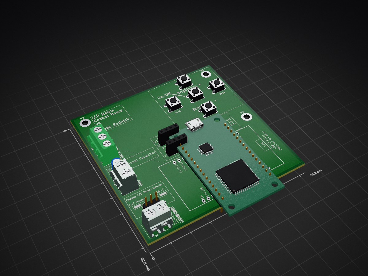
LED Matrix Sim is an open-source printed circuit board by IsaacRudnick, from the IsaacRudnick/LED-Matrix-Sim repository on GitHub. It is a 2-layer board of 83.2 × 82.6 mm with 21 parts on 31 nets, routed with 65 tracks and 0 vias.
Its parts include 5 resistors, 5 connectors and 5 switches. It belongs with the lEDs and displays boards of this library.
A collection of visual simulations for a 16x16 WS2812B LED matrix, powered by ESP32.
| Name | Description | Reset Condition |
|---|---|---|
| Game of Life | Conway's cellular automaton with RGB color mixing. Cells inherit averaged colors from parent neighbors. | Resets when pattern becomes stable |
| Langston's Ant | Turmite simulation where each ant follows a unique Turing machine ruleset: Red (RL - classic), Green (RLR - highway patterns), Blue (LLRR - symmetric), Yellow (LRRL - chaotic). Ants spawn at random positions and wrap around edges. | Never (continuous) |
| Brian's Brain | Three-state cellular automaton. Cells are Off, On, or Dying. Off cells with exactly 2 On neighbors turn On; On cells become Dying; Dying cells turn Off. Creates chaotic, self-sustaining patterns. | Resets when pattern becomes stable |
| Fire | Heat-based fire effect using a palette from black through red, orange, yellow to white. | Never (continuous) |
| Rain | Falling raindrops with trails against a dark blue background. | Never (continuous) |
| Sleep | Static moon + ZZ icon at minimal brightness for nighttime use. | Never (static) |
| Component | Details |
|---|---|
| MCU | ESP-32S Dev Module |
| LED Matrix | 16×16 WS2812B flexible matrix |
| Buttons | 5× momentary tactile pushbuttons |
| Connectors | 1× 2-pin Phoenix connector, 1× 3-pin Phoenix connector |
PCB design files are in KiCad/. GerberOrder_v3.zip contains ready-to-order Gerbers.
The LED matrix is powered directly from the ESP-32S's VIN pin (5V), which is why MAX_BRIGHTNESS is kept low — drawing too much current through VIN can cause instability. The data line connects to GPIO 26. Each button connects between its GPIO pin and GND; the ESP-32S's internal pullups keep the lines high when the button is open — no external pull-up resistors are needed on the PCB.
| Button | GPIO |
|---|---|
| Brightness Down | 16 |
| Next Simulation | 17 |
| Brightness Up | 18 |
| Previous Simulation | 19 |
| On / Off | 5 |
| Button | Action |
|---|---|
| Next Sim | Cycles sub-modes within the current simulation first; once all sub-modes are exhausted, advances to the next simulation |
| Prev Sim | Cycles sub-modes in reverse; once at sub-mode 0, goes back to the previous simulation at its last sub-mode |
| Brightness Up / Down | Adjusts brightness in steps between MIN_BRIGHTNESS and MAX_BRIGHTNESS |
| On / Off | Toggles the display; off state shows a dim sleep icon |
The current simulation, sub-mode, brightness, and on/off state are saved to EEPROM and restored on power-up.
Print files are in the print_files/ directory. Each file contains exactly the quantity needed — print one of each.
| File | Material | Notes |
|---|---|---|
FrontPlate.step | White PLA → Black PLA | See filament change instructions below |
BackPanel.step | Any | — |
SupportArms.step | Any | Contains both arms (left and right mirror) |
CrossBar.step | Any | — |
The front plate has a solid face followed by a raised grid pattern. Print the first layers in white PLA, then pause and switch to black (or other dark) filament at the layer where the grid begins to appear.
The solid white face must be at least 2 layers thick before the grid emerges — 3 layers works well. Set your layer height accordingly and add the filament-change pause in your slicer at the correct layer.
BackPanel — Press an M3 nut into each of the 3 hexagonal recesses on the back. Mount the PCB onto the front face of the panel using M3×10 screws through the PCB into the nuts.
SupportArms — Snap both arms into the back panel, then slide them into the dovetail slots on the front plate.
CrossBar — Press the crossbar between the two arms until it friction-fits into place.
Requires PlatformIO.
# Build
pio run

# Upload
pio run -t upload

# Monitor serial output
pio device monitor
You can also use the PlatformIO IDE in VSCode for a more integrated experience. I recommend this.
Note that if your upload fails, you may need to install the CP210x USB to UART Bridge VCP Drivers for your operating system.
include/
├── Config.h              # Pin definitions, dimensions, timing constants
├── Display.h             # LED buffer and animation functions
├── Simulation.h          # Base class interface for all simulations
└── simulations/
    ├── GameOfLife.h
    ├── LangstonAnt.h
    ├── BriansBrain.h
    ├── Fire.h
    ├── Rain.h
    └── SleepMode.h
src/
├── main.cpp              # Setup, loop, simulation registry
├── Display.cpp           # showBuffer, fadeOut, sweepIn, mapXYtoIndex
└── simulations/
    ├── GameOfLife.cpp
    ├── LangstonAnt.cpp
    ├── BriansBrain.cpp
    ├── Fire.cpp
    ├── Rain.cpp
    └── SleepMode.cpp
print_files/
├── FrontPlate.step
├── BackPanel.stepinclude/simulations/YourSim.h:#ifndef YOURSIM_H
#define YOURSIM_H
#include "Simulation.h"
class YourSim : public Simulation {
public:
void init() override;
bool update() override;
void render(uint8_t buffer[HEIGHT][WIDTH][3]) override;
uint16_t getFrameDelayMs() override { return 33; }
bool shouldReset() override { return false; }
const char* getName() override { return "Your Sim"; }
private:
// Your state here
};
#endifCreate implementation in src/simulations/YourSim.cpp
Add to main.cpp:
#include "simulations/YourSim.h"

YourSim yourSim;

Simulation* simulations[] = {
    // ... existing simulations
    &yourSim,
    &sleepMode  // Keep sleep last
};Key constants in include/Config.h:
| Constant | Default | Description |
|---|---|---|
DEFAULT_BRIGHTNESS | 20 | Normal brightness (0-255) |
SLEEP_BRIGHTNESS | 1 | Sleep mode brightness |
DEBOUNCE_DELAY_MS | 50 | Button debounce time |
FADE_STEPS | 20 | Animation smoothness |
SWEEP_TIME_MS | 1500 | Transition sweep duration |
Simulation-specific constants are in their respective header files.
| Qty | Value | Footprint | References |
|---|---|---|---|
| 5 | 10k | Resistor_THT:R_Axial_DIN0207_L6.3mm_D2.5mm_P10.16mm_Horizontal | R6, R7, R8, R9, R10 |
| 3 | Conn_01x01 | MountingHole:MountingHole_3.2mm_M3_DIN965_Pad | M1, M2, M3 |
| 2 | Conn_01x02 | TerminalBlock:TerminalBlock_MaiXu_MX126-5.0-02P_1x02_P5.00mm | J2, J3 |
| 2 | Conn_01x04 | Connector_PinSocket_2.54mm:PinSocket_1x04_P2.54mm_Vertical | J4, J5 |
| 1 | C_Polarized | Capacitor_THT:CP_Radial_D5.0mm_P2.50mm | 0.1uF1 |
| 1 | Conn_01x03 | TerminalBlock:TerminalBlock_MaiXu_MX126-5.0-03P_1x03_P5.00mm | J1 |
| 1 | Jumper_3_Open | Connector_PinHeader_2.54mm:PinHeader_1x03_P2.54mm_Vertical | JP1 |
| 1 | SW_PushDown | Button_Switch_THT:SW_PUSH_6mm | SW6 |
| 1 | SW_PushLeft | Button_Switch_THT:SW_PUSH_6mm | SW3 |
| 1 | SW_PushMid | Button_Switch_THT:SW_PUSH_6mm | SW1 |
| 1 | SW_PushRight | Button_Switch_THT:SW_PUSH_6mm | SW4 |
| 1 | SW_PushUp | Button_Switch_THT:SW_PUSH_6mm | SW2 |
| 1 | ~ | ESP32-DevKit-V1-DOIT-main:ESP32_30pin_NoMountingHoles | ESP32 |
gusmanb/logicanalyzer
24 channel, 100Msps logic analyzer hardware and software

mntmn/amiga2000-gfxcard
MNT VA2000, an Open Source Amiga 2/3/4000 Graphics Card (Zorro II/III), written in Verilog


hackclub/OnBoard
💡 Join 1,000 teenagers and make your first PCB with a $100 grant!

drandyhaas/KiCadRoutingTools
A set of Python/Rust tools to aid routing in KiCad

Arrow-air/project-quiver
Project Quiver documentation, designs, and project artifacts.


It measures 83.2 × 82.6 mm and has 2 copper layers, 1.6 mm thick.
21 parts. The full list of its parts is on this page, with links to each part's symbol and footprint where PCBKit's library has them.
From the IsaacRudnick/LED-Matrix-Sim repository on GitHub, at the commit this page was made from: the board is KiCad/KiCad.kicad_pcb and its schematic KiCad/KiCad.kicad_sch. PCBKit opens the board in the browser, with nothing to install.
Its repository states no licence, so its author keeps all rights: ask IsaacRudnick before reusing the design.