

2 layers50.2 × 34.9 mm

 ImoogDi/2MoreVO1
Eurorack dual VCO using the public AS3340/CEM3340
2MoreVO is an open-source printed circuit board by ImoogDi, from the ImoogDi/2MoreVO repository on GitHub. It is a 2-layer board of 76.2 × 157.5 mm with 142 parts on 135 nets, routed with 1,158 tracks and 115 vias.
It is built around the TL072 and BAT46. Its parts include 55 resistors, 22 connectors, 16 capacitors, 8 diodes and 6 switches. It belongs with the audio and music boards of this library.
Eurorack Dual VCO using the public CEM3340/AS3340 chip.
Table of Contents
This eurorack-modul is designed for modular-synthesizers as dual Voltage Controlled Oscillator.
The oszillators are build around two IC's: AS3340, a clone of that wellknown CEM3340.
Another benifit is the three cannel VCA: AS3363 included to control the modulation-level, waveform output of VCO1 and oscillator-signal fading between VCO1- and VCO2-outputs.
The '2MoreVO'-PCB's are:
All parts are common available and DIY-friendly designed, most parts are SMD on the VCO-PCB's.
(Details see attached pictures)
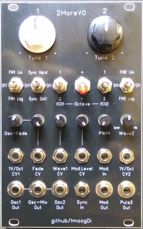
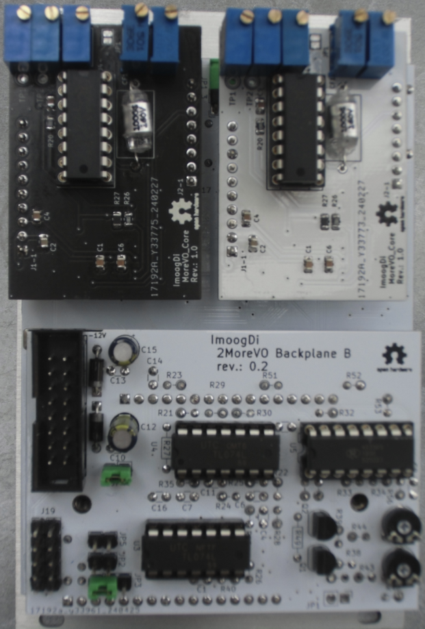
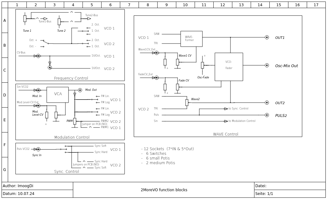
| Jack-Name | Function | Comment | Detail |
|---|---|---|---|
| 1V/Oct CV1 | CV-input for VCO1 pitch control | fixed 1Volt/Octave scaling | This input is normalised with the eurobus Control-Voltage and connected with the '1V/Oct CV2' input. Patch-cabel plugged in breaks the default connection to eurobus CV but the connection to '1V/Oct CV2' is still available. |
| Fade CV | CV-input for fading oscillator-signals | The Fading between Osc1- and Osc2-signals on 'Osc-Mix Out' is controlled with this CV | CV level adjustable between 0 ... max. with 'Fade CV'-pot. works together with 'Osc-Fade'-pot. Bipolar signal input. |
| Wave1 CV | CV-input for VCO1 wave-control | The waveform on 'Osc1 Out' is controlled with this CV | CV Level adjustable between 0 ... max. with 'Wave1 CV'-pot. Bipolar signal input. |
| Mod.Level CV | CV-input for modulation level control | Control of modulation level on 'Mod Out' | Modulation Level adjustable between 0 ... max. with 'Mod.Level CV'-pot. Bipolar signal input. |
| Mod. In | Modulation signal input | input for external signals controlling FM(Lin/Log) and PWM on Osc1 and Osc2 | This input is normalised with the sinusoidal-signal from Osc2 if no signal is plugged in. Bipolar signal input. |
| 1V/Oct CV2 | CV-input for VCO2 pitch control | fixed 1Volt/Octave scaling | This input is normalised with the '1V/Oct CV1' input. Patch-cabel plugged in breaks the default connection to '1V/Oct CV1'. |
| Osc1 Out | output for VCO1-oscillator signal | triangle- to saw-waveform output, morvable manually or with external CV | Waveform morvable with 'Wave1 CV'-pot and CV-signal. |
| Osc-Mix Out | output for mixed VCO1-/VCO2-oscillator signal | mixed signal from Osc1- and Osc2-outputs | Waveforms fadeable between Osc1- and Osc2-signal outputs. Fading can be done with 'Fade CV'-pot and CV-signal. 50%/50% Osc1/2-signal level on 'Osc-Mix Out', if 'Osc-Fade'-pot is in centerposition and no 'Fade CV' is plugged in. |
| Osc2 Out | output for VCO2-oscillator signal | saw- to triangle-waveform output, morvable manually | Waveform morvable with 'Wave2'-pot between saw- and triangle-signal. |
| Sync In | Sync-signal for VCO1 (optional VCO2) | this signal can be switched to: 'Sync Hard', ' Sync Soft' or 'Off' | This input is normalised with the 'Puls2 Out'-signal from VCO2. Patch-cabel plugged in breaks the default connection to 'Puls2 Out'. |
| Mod Out | output for modulation-signal controllable with 'Mod.Level CV' | modulation-signal used for 'FMx Lin/Log' and 'PWM' default sinusoidal-signal from VCO2 used for VCO1 modulation | sinusoidal-signal from VCO2 is available on this output if high impedance connection is used. optional an external low impedance signal plugged in can overwride the internal modulation. |
| Puls2 Out | output for puls-signal from VCO2 | output-signal for synchronisation and audio the pulswith is controllable with 'PWM'-pot using the 'Mod Out'-signal | This output is also internally linked to 'Sync In'. Bipolar output with +-5.0Volt level. |
There are eight potentiometers with following functions:
| Pot-Name | Function | Comment | Detail |
|---|---|---|---|
| Tune 1 | Pitch for VCO1 | default pitch in center-position | tuning-range +-2 octaves. |
| Tune 2 | Pitch for VCO2 | default pitch in center-position | tuning-range +-2 octaves. |
| Osc-Fade | manually fading between Osc1- and Osc2-signals on 'Osc-Mix Out' | works as CV offset for the 'Fade CV'-signal | pot to CCW: Osc2-signal output. pot to CW: Osc1-signal output. pot to centerposition: equal level output. |
| Fade CV | CV Level amount pot for fading between Osc1- and Osc2-signals on 'Osc-Mix Out' | works together with 'Osc-Fade' for fading Osc1/2-signals | CV Level adjustable between 0 ... max. |
| Wave1 CV | CV Level amount pot for Osc1 waveform-selection on 'Osc1 out' | manually selection of waveform is possible if no CV-signal is plugged in | CV Level adjustable between 0 ... max. |
| Mod.Level CV | CV Level amount pot for modulation control | manually modulationlevel control is possible if no CV-signal is plugged in | CV Level adjustable between 0 ... max. |
| PWM | pulswith pot to control amount of PWM | the modulation-signal on 'Mod Out' is used for PWM | PWM amount adjustable between 0 ... max. Pulswith is 50% on 'Puls2 Out' if pot is in CCW-position (set to 0). |
| Wave2 | waveform selection pot for Osc2-signal | manually morving between saw- and triangle-signal | pot to CCW: SAW-signal. pot to CW: Triangle-signal. pot to centerposition: mixed signal. |
There are six switches to control the behaviour of signals.
| Switch | Function | Comment | Detail |
|---|---|---|---|
| FM1-switch | switch for VCO1 FM modulation using signal on 'Mod Out' | FM controll for VCO1 | FM1 Lin := Linear FM modulation. Off := function off. FM1 Log := Logarithmic FM modulation. |
| Sync-switch | switch for VCO1 Hard- or Soft-synchronisation with puls-signal from VCO2 | switched synchronisation-signal from 'Puls2 Out' | Sync Hard := hard synced to VCO2. Off := sync. function off. Sync Soft := soft synced to VCO2. |
| VCO1 Octave-switch | switch for VCO1 pitch setting | octaves up or down depending on 'Octave switch + or -' | 1 := one octave (up/down). 2 := two octaves (up/down). |
| Octave up/down switch | switch for VCO1- and VCO2-switched pitchcontrol | selecting pitch up or down for VCO1 and VCO2 | + := pitch up. - := pitch down. |
| VCO2 Octave-switch | switch for VCO2 pitch setting | octaves up or down depending on 'Octave switch + or -' | 1 := one octave (up/down). 2 := two octaves (up/down). |
| FM2-switch | switch for VCO2 FM modulation using signal on 'Mod Out' | FM controll for VCO2 | FM1 Lin := Linear FM modulation. Off := function off. FM1 Log := Logarithmic FM modulation. |
size:
width: 16HP
depth: 45mm
power:
5Volt, 0 mA
+12Volt, 60mA
-12Volt, 60mA
frequency range: 20Hz to 20kHz.
frequency CV scale: 1V/Oct on '1V/Oct CV1'- and '1V/Oct CV2'-inputs.
frequency pot tuning range: +-2 Octaves.
frequency switchable pitch range: plus or minus 1 or 2 octaves for oscillator 1/2.
signal inputs, DC-coupled signal path.
signal outputs, DC-coupled signal path.
signal input impedance: > 50kOhm.
signal output impedance: 500 Ohm.
expandable with more '2MoreVO' dual-oscillator('s) used in master-/slave-configuration.
Hardware:cc by-nc-sa 4.0 (details)
| Qty | Value | Footprint | References |
|---|---|---|---|
| 12 | AudioJack2_SwitchT | Connector_Audio:Jack_3.5mm_QingPu_WQP-PJ398SM_Vertical_CircularHoles | J1, J2, J3, J4, J5, J6, J9, J10, J11, J12, J13, J14 |
| 11 | 100nF | Capacitor_THT:C_Disc_D3.0mm_W1.6mm_P2.50mm | C1, C2, C3, C5, C8, C9, C10, C11, C13, C14, C16 |
| 6 | 100K | Potentiometer_THT:Potentiometer_Alps_RK09K_Single_Vertical | RV4, RV5, RV6, RV7, RV8, RV10 |
| 6 | 10K | Resistor_THT:R_Axial_DIN0204_L3.6mm_D1.6mm_P7.62mm_Horizontal | R5, R9, R10, R12, R13, R57 |
| 6 | 1K | Resistor_THT:R_Axial_DIN0204_L3.6mm_D1.6mm_P2.54mm_Vertical | R20, R28, R31, R48, R50, R53 |
| 6 | BAT46 | Diode_THT:D_DO-35_SOD27_P7.62mm_Horizontal | D1, D2, D7, D9, D10, D11 |
| 5 | 100K | Resistor_THT:R_Axial_DIN0204_L3.6mm_D1.6mm_P2.54mm_Vertical | R23, R24, R25, R29, R51 |
| 5 | 10K | Resistor_THT:R_Axial_DIN0204_L3.6mm_D1.6mm_P2.54mm_Vertical | R36, R38, R39, R40, R44 |
| 5 | SW_SPDT_MSM | PCM_4ms_Switch:Switch_Toggle_SPDT_Mini_SolderLug | SW1, SW3, SW4, SW5, SW6 |
| 4 | 27K(15K) | Resistor_THT:R_Axial_DIN0204_L3.6mm_D1.6mm_P7.62mm_Horizontal | R14, R15, R16, R17 |
| 4 | 47K | Resistor_THT:R_Axial_DIN0204_L3.6mm_D1.6mm_P2.54mm_Vertical | R18, R21, R30, R35 |
| 4 | 47K | Resistor_THT:R_Axial_DIN0204_L3.6mm_D1.6mm_P7.62mm_Horizontal | R46, R47, R54, R55 |
| 4 | MountingHole_3.2mm_M3 | MountingHole:MountingHole_3.2mm_M3 | REF_L1, REF_L2, REF_L3, REF_L4 |
| 3 | 100K | Resistor_THT:R_Axial_DIN0204_L3.6mm_D1.6mm_P7.62mm_Horizontal | R3, R6, R45 |
| 3 | 150K | Resistor_THT:R_Axial_DIN0204_L3.6mm_D1.6mm_P2.54mm_Vertical | R19, R22, R52 |
| 3 | 2.7K | Resistor_THT:R_Axial_DIN0204_L3.6mm_D1.6mm_P2.54mm_Vertical | R32, R33, R34 |
| 3 | 27pF | Capacitor_THT:C_Disc_D3.0mm_W1.6mm_P2.50mm | C4, C6, C7 |
| 3 | 470 | Resistor_THT:R_Axial_DIN0204_L3.6mm_D1.6mm_P7.62mm_Horizontal | R1, R2, R4 |
| 3 | Jumper_2_Open | Connector_PinHeader_2.54mm:PinHeader_1x02_P2.54mm_Horizontal | JP1_1, JP1_2, JP1_3 |
| 2 | 100K(50K) lin. | Potentiometer_THT:Potentiometer_Alps_RK09K_Single_Vertical | RV2, RV3 |
| 2 | 1N4001 | Diode_THT:D_DO-35_SOD27_P7.62mm_Horizontal | D8, D12 |
| 2 | 20K | Resistor_THT:R_Axial_DIN0204_L3.6mm_D1.6mm_P2.54mm_Vertical | R43, R56 |
| 2 | 22u | Capacitor_THT:CP_Radial_D5.0mm_P2.50mm | C12, C15 |
| 2 | 2N3904 | Package_TO_SOT_THT:TO-92_Inline | Q1, Q2 |
| 2 | 5K | Potentiometer_THT:Potentiometer_Bourns_3006P_Horizontal | RV1, RV12 |
| 2 | Conn_01x08_Socket | Connector_PinSocket_2.54mm:PinSocket_1x08_P2.54mm_Vertical | J15, J17 |
| 2 | Conn_01x10_Socket | Connector_PinSocket_2.54mm:PinSocket_1x10_P2.54mm_Vertical | J16, J18 |
| 2 | Conn_01x16_Pin | Connector_PinHeader_2.54mm:PinHeader_1x16_P2.54mm_Vertical | J21, J23 |
| 2 | Conn_01x16_Socket | Connector_PinSocket_2.54mm:PinSocket_1x16_P2.54mm_Vertical | J7, J8 |
| 2 | Jumper_3_Open | Connector_PinHeader_2.54mm:PinHeader_1x03_P2.54mm_Vertical | JP1, JP3 |
| 2 | OSHW-Logo2_7.3x6mm_SilkScreen | Symbol:OSHW-Logo2_7.3x6mm_SilkScreen | REF_A, REF_B |
| 2 | TL074 | Package_DIP:DIP-14_W7.62mm | U3, U4 |
| 1 | +2V | TestPoint:TestPoint_Keystone_5000-5004_Miniature | TP1 |
| 1 | -2V | TestPoint:TestPoint_Keystone_5000-5004_Miniature | TP2 |
| 1 | 10K | Potentiometer_THT:Potentiometer_Piher_PT-6-V_Vertical | RV11 |
| 1 | 150K | Resistor_THT:R_Axial_DIN0204_L3.6mm_D1.6mm_P7.62mm_Horizontal | R27 |
| 1 | 1K | Resistor_THT:R_Axial_DIN0204_L3.6mm_D1.6mm_P7.62mm_Horizontal | R7 |
| 1 | 2,7K | Resistor_THT:R_Axial_DIN0204_L3.6mm_D1.6mm_P7.62mm_Horizontal | R8 |
| 1 | 390 | Resistor_THT:R_Axial_DIN0204_L3.6mm_D1.6mm_P7.62mm_Horizontal | R49 |
| 1 | 470 | Resistor_THT:R_Axial_DIN0204_L3.6mm_D1.6mm_P2.54mm_Vertical | R42 |
| 1 | 50K | Potentiometer_THT:Potentiometer_Piher_PT-6-V_Vertical | RV9 |
| 1 | 51K | Resistor_THT:R_Axial_DIN0204_L3.6mm_D1.6mm_P7.62mm_Horizontal | R37 |
| 1 | 6,8K | Resistor_THT:R_Axial_DIN0204_L3.6mm_D1.6mm_P7.62mm_Horizontal | R11 |
| 1 | AS3363 | Package_DIP:DIP-16_W7.62mm | U5 |
| 1 | Conn_02x05_Odd_Even | Connector_PinHeader_2.54mm:PinHeader_2x05_P2.54mm_Vertical | J19 |
| 1 | Conn_02x08_Odd_Even | PCM_4ms_Connector:Pins_2x08_2.54mm_TH_EuroPower_Shrouded_reducedsilk_pins_assignment | J22 |
| 1 | Jumper_2_Bridged | Connector_PinHeader_2.54mm:PinHeader_1x02_P2.54mm_Vertical | JP4 |
| 1 | Jumper_2_Open | Connector_PinHeader_2.54mm:PinHeader_1x02_P2.54mm_Vertical | JP2 |
| 1 | SIN2 | TestPoint:TestPoint_Keystone_5000-5004_Miniature | TP3 |
| 1 | SW_SPDT | PCM_4ms_Switch:Switch_Toggle_SPDT_Mini_SolderLug | SW2 |
| 1 | TL072 | Package_DIP:DIP-8_W7.62mm | U2 |
| 1 | TL431LP | Package_TO_SOT_THT:TO-92_Inline | U1 |

cyberboy666/recurBOY
a rpi0 video-instrument – created in collaboration with Guergana Tzatchkova

cyberboy666/sync_ope
effect send + sync restoring circuit - adapted from a gael jaton design

robsonsmartins/usbflashprog
A memory device programmer (Flash/EPROM/E2PROM) board and software, connected to PC by USB port.

mariusgreuel/EMS-Bus-Gateway
EMS Bus Gateway for Buderus Boilers to run EMS-ESP32

cyberboy666/i_n_c_u_r
a r_e_c_u_r video sampler extension circuit - adding knobs, cv and serial midi control

CosmicPi/CosmicPiV1.7PCB
PCB for Version 1.7 of the Cosmic Pi Hardware. Incremental changes from V1.6. This design is licensed under the CERN OHL V1.2


It measures 76.2 × 157.5 mm and has 2 copper layers, 1.6 mm thick.
142 parts, built around the TL072 and BAT46. The full list of its parts is on this page, with links to each part's symbol and footprint where PCBKit's library has them.
From the ImoogDi/2MoreVO repository on GitHub, at the commit this page was made from: the board is hw/2MoreVO.kicad_pcb and its schematic hw/2MoreVO.kicad_sch. PCBKit opens the board in the browser, with nothing to install.
Its repository states no licence, so its author keeps all rights: ask ImoogDi before reusing the design.