

4 layers81.2 × 96.6 mm
 Hirusha785/433MHz-ASK-Receiver-Module1
📡 Compact 433MHz ASK RF receiver PCB with antenna input matching, signal detection, LM358 amplification, filtering, and digital output for embedded wireless applications. 🧠 More Advanced Version
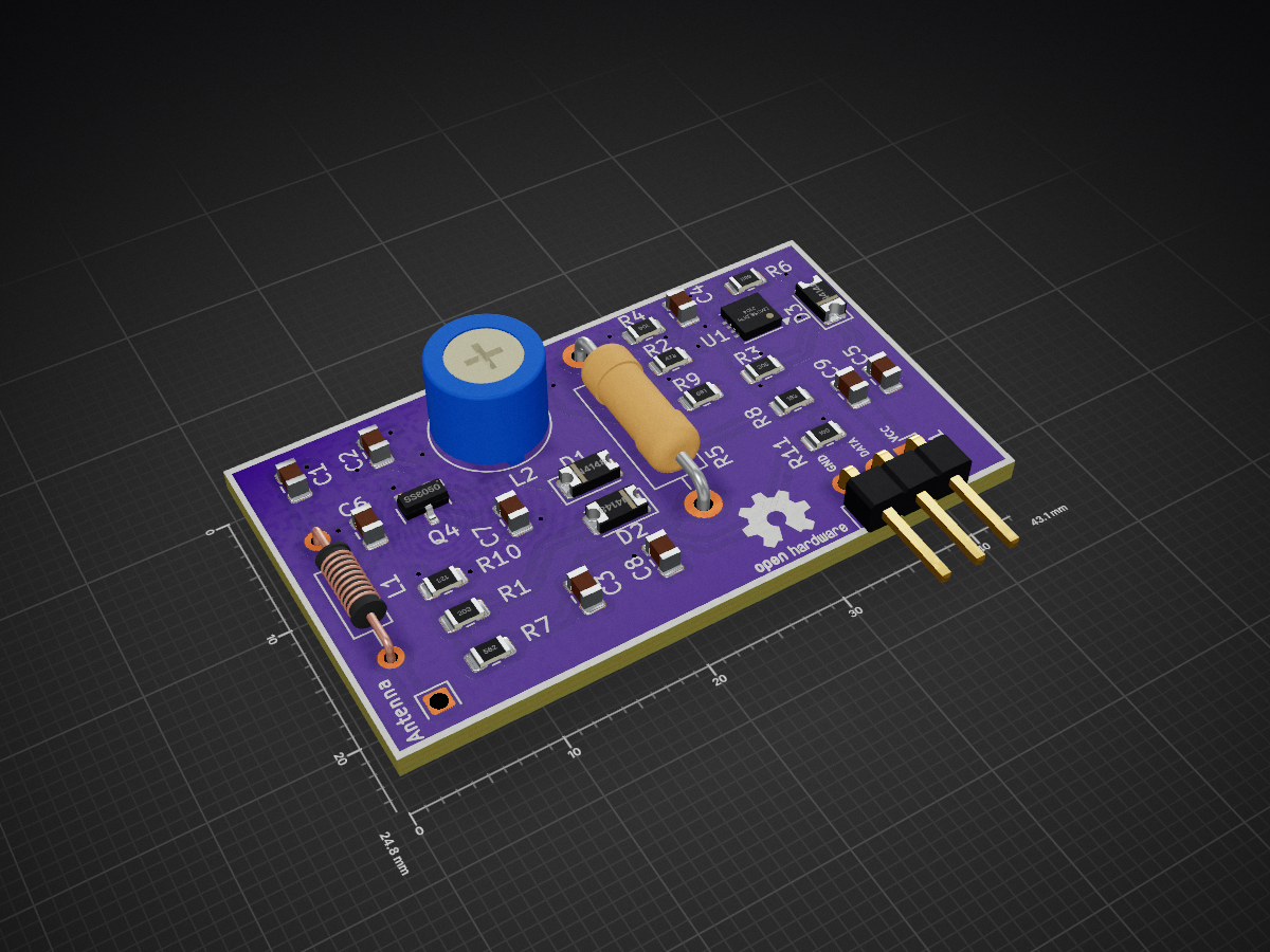
433 MHz RF Modules is an open-source printed circuit board by Hirusha785, from the Hirusha785/433MHz-ASK-Receiver-Module repository on GitHub, published under the MIT licence. It is a 4-layer board of 43.1 × 24.8 mm with 30 parts on 17 nets, routed with 152 tracks and 25 vias.
It is built around the SS8050. Its parts include 11 resistors, 9 capacitors, 3 diodes, 2 inductors and 1 IC. It belongs with the radio and wireless and sensors and measurement boards of this library.




433MHz ASK RF Receiver Module is a compact open-hardware wireless receiver PCB designed for receiving 433MHz Amplitude Shift Keying signals in embedded systems, IoT projects, RF learning setups, remote-control decoding experiments, and custom wireless communication applications.
The design includes an antenna input stage, RF tuning section, transistor-based RF front-end, diode-based signal detection, filtering network, and LM358-based analog signal conditioning to provide a usable output signal for microcontrollers, decoder circuits, oscilloscopes, or logic analyzers.
This module is designed to receive wireless signals in the 433MHz ISM frequency band using ASK modulation.
The incoming RF signal is captured by the antenna and passed through a tuned RF input network. The signal is then processed through the RF front-end stage, detected using diode-based rectification, filtered using resistor-capacitor networks, and conditioned using LM358 operational amplifier stages.
The final output can be connected to a microcontroller GPIO pin, oscilloscope, logic analyzer, decoder circuit, or embedded system for further processing.
Antenna
   ↓
RF Input Matching / Tuning
   ↓
RF Front-End Stage
   ↓
ASK Signal Detection
   ↓
Noise Filtering
   ↓
LM358 Signal Conditioning
   ↓
DATA Output
   ↓
Microcontroller / Decoder / Logic Analyzer| Pin | Name | Description |
|---|---|---|
| 1 | VCC | Power input |
| 2 | DATA | Receiver output signal |
| 3 | GND | Ground |
| Component | Function |
|---|---|
| Antenna | Captures 433MHz RF signals |
| Inductors | RF tuning and filtering |
| Capacitors | Coupling, filtering, and decoupling |
| Diodes | Signal detection |
| Transistor | RF front-end signal handling |
| LM358 | Amplification and analog signal conditioning |
| Resistors | Biasing, gain setting, and filtering |
| Header Pins | External power and signal interface |
The antenna input receives the 433MHz RF signal.
A properly tuned antenna improves sensitivity, stability, and range.
The LC components are used to tune and filter the received RF signal.
This section helps improve selectivity around the 433MHz frequency range.
The transistor stage helps process the weak RF input signal before detection.
The diode stage detects amplitude changes in the received RF signal and converts them into a lower-frequency signal component.
RC filters smooth the detected signal and reduce unwanted RF noise.
The LM358 operational amplifier stages amplify and condition the detected signal so it can be used by external digital or analog circuits.
The output pin provides the recovered receiver signal for further processing.
You can test this receiver module using:
Example testing flow:
433MHz ASK Transmitter
        ↓
433MHz ASK Receiver Module
        ↓
Microcontroller GPIO
        ↓
Serial Monitor / Decoder Software#define RF_DATA_PIN 2
void setup() {
Serial.begin(9600);
pinMode(RF_DATA_PIN, INPUT);
}
void loop() {
int rfSignal = digitalRead(RF_DATA_PIN);
Serial.println(rfSignal);
delay(10);
}#define RF_DATA_PIN 27
void setup() {
Serial.begin(115200);
pinMode(RF_DATA_PIN, INPUT);
}
void loop() {
int signalState = digitalRead(RF_DATA_PIN);
Serial.println(signalState);
delay(10);
}Recommended test points:
| Test Point | Purpose |
|---|---|
| Antenna input | Check received RF activity |
| Detector output | View detected ASK signal |
| LM358 output | Check conditioned output signal |
| DATA pin | Final receiver output |


For better range and sensitivity, use a properly sized antenna.
A common quarter-wave antenna length for 433MHz is approximately:
17.3 cmA simple wire antenna can be used for testing, but performance depends on placement, wire quality, ground reference, and surrounding interference.
This module is intended for:
RF performance depends on:
This hardware should be tested and certified according to local RF regulations before any commercial deployment.
Designed by Fernando S.M.H.G
Open-hardware RF receiver project for embedded systems, electronics learning, and wireless communication experiments.
This project is released under the MIT License.
You are free to use, modify, improve, and share this project with proper attribution.
If this project helps you, consider giving the repository a star.
Made for RF learning, embedded systems, and open-hardware development.| Qty | Value | Footprint | References |
|---|---|---|---|
| 3 | 1N4148 | Diode_SMD:D_1206_3216Metric | D1, D2, D3 |
| 2 | 1 nF | Capacitor_SMD:C_0805_2012Metric | C2, C3 |
| 2 | 2 pF | Capacitor_SMD:C_0805_2012Metric | C6, C7 |
| 2 | 4.7 uF | Capacitor_SMD:C_0805_2012Metric | C4, C5 |
| 1 | 1.5 turns | Inductor_THT:L_Axial_L5.3mm_D2.2mm_P10.16mm_Horizontal_Vishay_IM-1 | L1 |
| 1 | 10 | Resistor_SMD:R_0805_2012Metric | R11 |
| 1 | 10 uF | Capacitor_SMD:C_0805_2012Metric | C9 |
| 1 | 100k | Resistor_THT:R_Axial_DIN0411_L9.9mm_D3.6mm_P15.24mm_Horizontal | R5 |
| 1 | 100k | Resistor_SMD:R_0805_2012Metric | R4 |
| 1 | 12k | Resistor_SMD:R_0805_2012Metric | R10 |
| 1 | 18k | Resistor_SMD:R_0805_2012Metric | R8 |
| 1 | 2 uH | Potentiometer_THT:Potentiometer_Bourns_3339P_Vertical_HandSoldering | L2 |
| 1 | 20k | Resistor_SMD:R_0805_2012Metric | R1 |
| 1 | 33 pF | Capacitor_SMD:C_0805_2012Metric | C1 |
| 1 | 3M | Resistor_SMD:R_0805_2012Metric | R3 |
| 1 | 47 uF | Capacitor_SMD:C_0805_2012Metric | C8 |
| 1 | 47k | Resistor_SMD:R_0805_2012Metric | R2 |
| 1 | 5.6k | Resistor_SMD:R_0805_2012Metric | R7 |
| 1 | 6.8M | Resistor_SMD:R_0805_2012Metric | R6 |
| 1 | 680 | Resistor_SMD:R_0805_2012Metric | R9 |
| 1 | Antenna | RF_Antenna:NiceRF_SW868-TH13_868Mhz | Antenna |
| 1 | Conn_01x03_Pin | Connector_PinHeader_2.54mm:PinHeader_1x03_P2.54mm_Horizontal | J1 |
| 1 | LM358_DFN | Package_DFN_QFN:DFN-8-1EP_3x3mm_P0.5mm_EP1.66x2.38mm | U1 |
| 1 | SS8050 | Package_TO_SOT_SMD:SOT-23 | Q4 |
The 29 most common of 30 parts.

bkshepherd/DaisySeedProjects
A collection of hardware and software projects based around the Electro-Smith Daisy Seed


ctag-fh-kiel/ctag-tbd
CTAG TBD >>to be determined<< an extendible open source Eurorack sound module


DerSpatz/PCB-reflow-solder-heat-plate
hardware design for a PCB reflow solder heat plate

GuitarML/GuitarPedalSTM32
Guitar pedal using a stm32h7 microcontroller programmed with CubeIDE (PCB and Firmware)
It measures 43.1 × 24.8 mm and has 4 copper layers, 1.6 mm thick.
30 parts, built around the SS8050. The full list of its parts is on this page, with links to each part's symbol and footprint where PCBKit's library has them.
From the Hirusha785/433MHz-ASK-Receiver-Module repository on GitHub, at the commit this page was made from: the board is 433 MHz RF Modules.kicad_pcb and its schematic 433 MHz RF Modules.kicad_sch. PCBKit opens the board in the browser, with nothing to install.
Its repository publishes it under the MIT licence: you may reuse it on that licence's terms (keep the author's notice, and for a copyleft licence share your changes alike).