2 layers18.5 × 11.1 mm
Switch
byrantech/laptop
anyon_e, a highly integrated, high end, open source laptop. Attempt the impossible.
6 parts4.3kMIT

 Harshavar8jdm/micro-sd-spi-breakout-module
A compact, high-performance, 2-layer MicroSD Card Breakout Board designed in KiCad for embedded microcontrollers using the SPI (Serial Peripheral Interface) bus.
Micro sd spi breakout module is an open-source printed circuit board by Harshavar8jdm, from the Harshavar8jdm/micro-sd-spi-breakout-module repository on GitHub. It is a 2-layer board of 28 × 22 mm with 6 parts on 9 nets, routed with 48 tracks and 12 vias.
Its parts include 2 capacitors, 2 resistors, 1 IC and 1 connector. It belongs with the interfaces and adapters boards of this library.
A compact, high-performance, 2-layer MicroSD Card Breakout Board designed in KiCad for embedded microcontrollers using the SPI (Serial Peripheral Interface) bus.
Designed specifically for 3.3V native logic ecosystems (STM32, ESP32, RP2040, SAMD, Nordic, etc.), this module provides clean power decoupling, signal pull-ups, and a low-EMI ground plane layout.
| Top View | Bottom View |
|---|---|
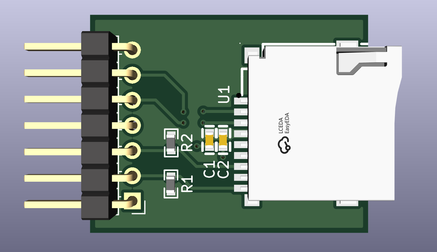 | 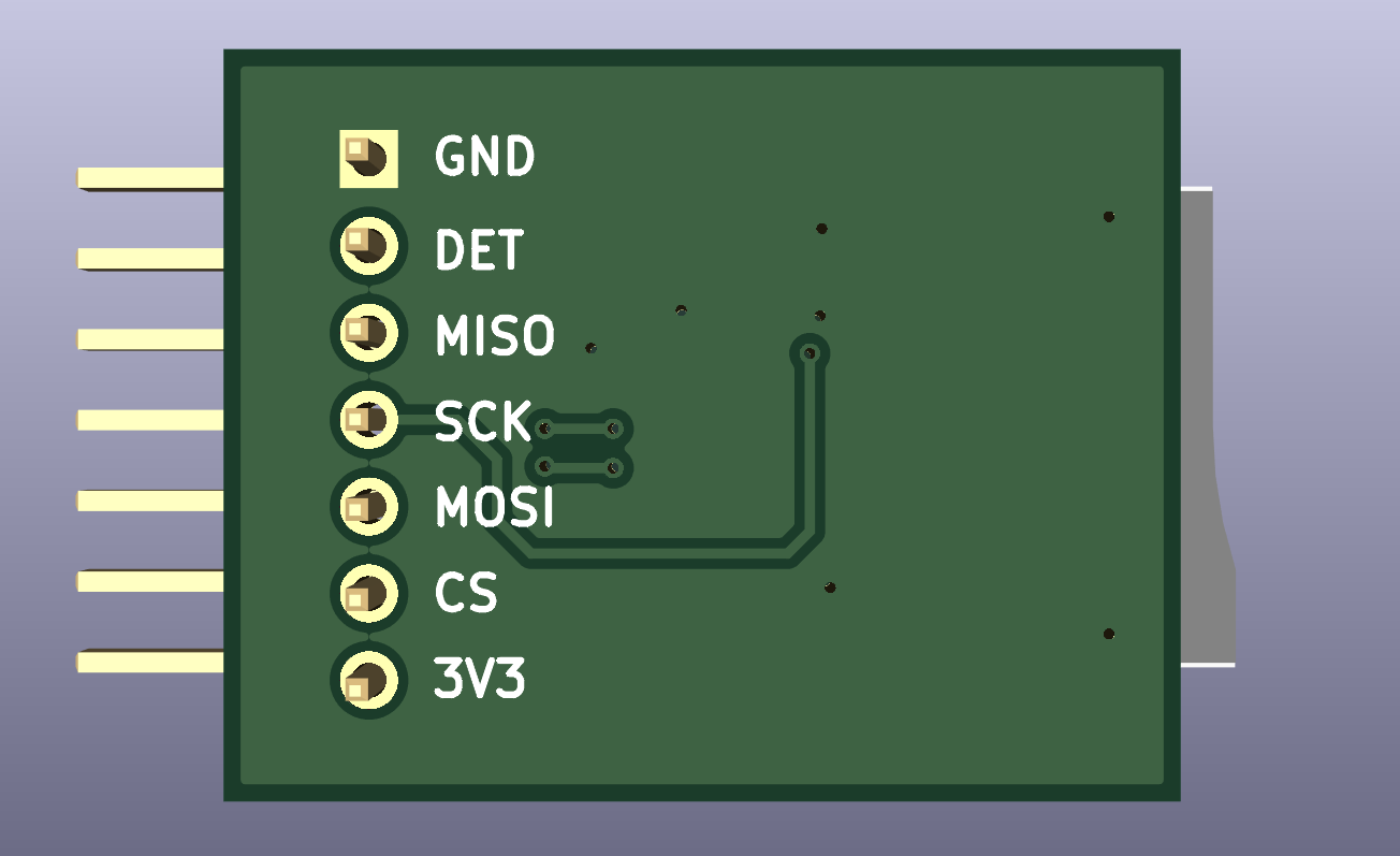 |
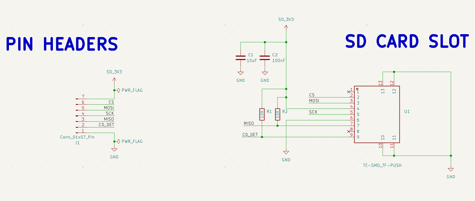
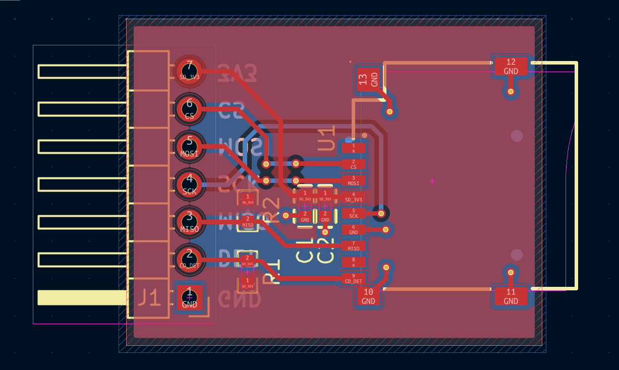
| Reference | Quantity | Value / Part | Footprint / Package | Description |
|---|---|---|---|---|
| U1 | 1 | TF_SMD_TF-PUSH | MicroSD Push-Push Connector | Surface Mount TF/MicroSD Socket |
| J1 | 1 | Conn_01x07_Pin | PinHeader 1x07, P2.54mm, Vertical | 0.1 inch Pitch Male Pin Header |
| C1 | 1 | 10 uF | Ceramic Cap, 0805 | Bulk Power Decoupling |
| C2 | 1 | 100 nF | Ceramic Cap, 0603 | High-Frequency Decoupling |
| R1, R2 | 2 | 10k Ohm | Resistor, 0603 | Signal Pull-Up Resistors |
When writing software/drivers for SD cards via SPI:
CMD0, CMD8, ACMD41) to be executed at a slow clock speed (<400 kHz) while the card initializes its internal state machine into SPI mode.SCK, MOSI, and CS lines to prevent over-voltage damage to the SD card.| Qty | Value | Footprint | References |
|---|---|---|---|
| 2 | 10K | 10K-Res:R0603_FRC0603F1001TS_C2907002 | R1, R2 |
| 1 | 100nF | 100nF-Cap:C0603_CC0603JRX7R9BB104_C91183 | C2 |
| 1 | 10uF | 10uF-Cap:C0603_CL10A106KP8NNNC_C19702 | C1 |
| 1 | Conn_01x07_Pin | Connector_PinHeader_2.54mm:PinHeader_1x07_P2.54mm_Horizontal | J1 |
| 1 | TF-SMD_TF-PUSH | Sd-Card-Holder:TF-SMD_TF-PUSH_TF_PUSH_C393941 | U1 |
byrantech/laptop
anyon_e, a highly integrated, high end, open source laptop. Attempt the impossible.


Jcparkyn/dpoint
Open-source digital stylus using camera tracking and inertial measurements

VoronDesign/Voron-Hardware
Cool Hardware designed by the Voron Design group

hoglet67/RGBtoHDMI
Bare-metal Raspberry Pi project that provides pixel-perfect sampling of Retro Computer RGB/YUV video and conversion to HDMI

hackclub/OnBoard
💡 Join 1,000 teenagers and make your first PCB with a $100 grant!

Luos-io/luos_engine
Open-source and real-time orchestrator for cyber-physical-systems, to easily design, test and deploy embedded applications and digital twins.

It measures 28 × 22 mm and has 2 copper layers, 1.6 mm thick.
6 parts. The full list of its parts is on this page, with links to each part's symbol and footprint where PCBKit's library has them.
From the Harshavar8jdm/micro-sd-spi-breakout-module repository on GitHub, at the commit this page was made from: the board is micro-sd-spi-breakout-module.kicad_pcb and its schematic micro-sd-spi-breakout-module.kicad_sch. PCBKit opens the board in the browser, with nothing to install.
Its repository states no licence, so its author keeps all rights: ask Harshavar8jdm before reusing the design.