
2 layers47.4 × 39.8 mm

 Harshavar8jdm/1S-Li-ion-Battery-Charger-Module
A single-cell (1S) Lithium-Ion / Lithium-Polymer battery charging PCB based on the Texas Instruments BQ24092 linear charger IC.
Li ion charger design is an open-source printed circuit board by Harshavar8jdm, from the Harshavar8jdm/1S-Li-ion-Battery-Charger-Module repository on GitHub. It is a 2-layer board of 40 × 11.5 mm with 14 parts on 22 nets, routed with 52 tracks and 9 vias.
It is built around the BQ24092DGQT. Its parts include 7 resistors, 2 capacitors, 2 diodes, 2 connectors and 1 IC. It belongs with the power boards of this library.
A single-cell (1S) Lithium-Ion / Lithium-Polymer battery charging PCB based on the Texas Instruments BQ24092 linear charger IC. The board uses a USB Type-C connector for 5V input, status LEDs for charge monitoring, and a 2-pin right-angle JST connector for battery attachment.
| Top Render | Bottom Render |
|---|---|
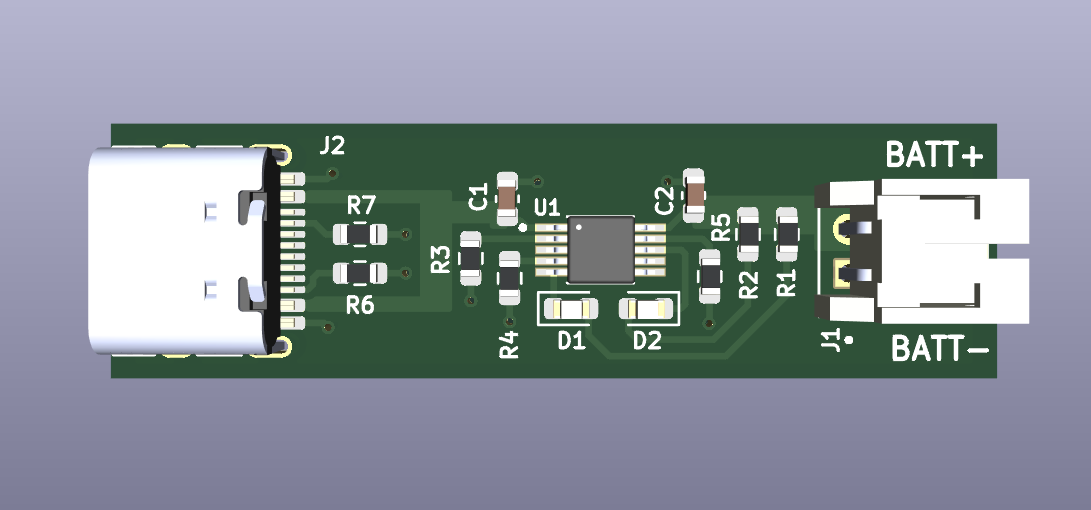 | 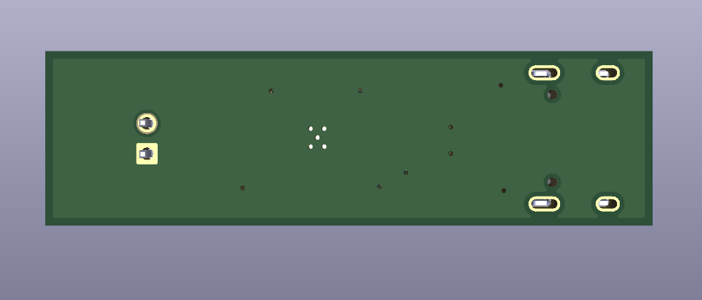 |
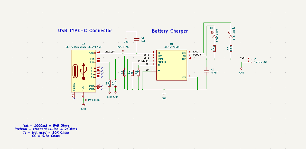
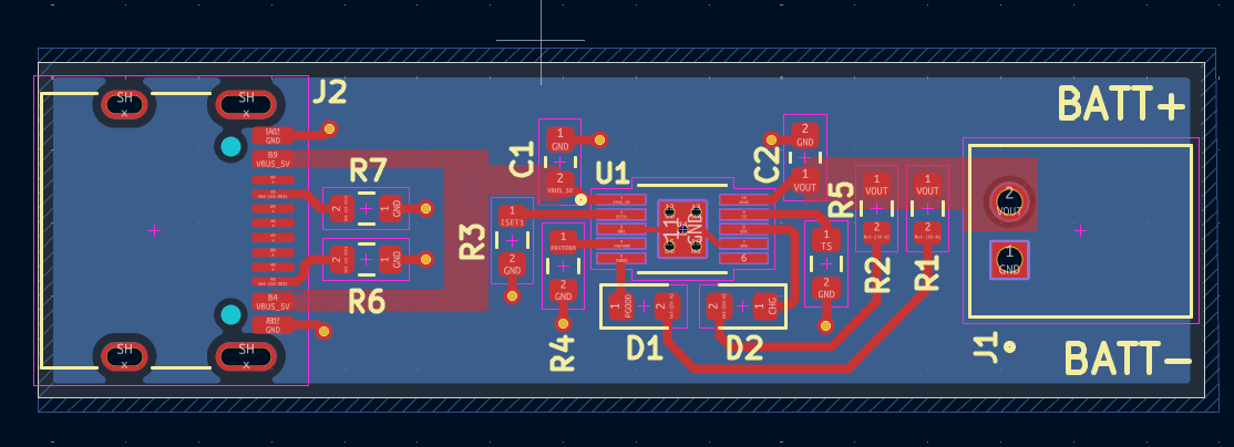
PG) and Charging (CHG) indication.J1) for single-cell battery connection.| Parameter | Value |
|---|---|
| Input Voltage ($V_{IN}$) | 5.0 V DC (via USB Type-C) |
| Charger IC | TI BQ24092DGQT (MSOP-PowerPAD-10) |
| Charge Current ($I_{CHG}$) | 1000 mA (1A) |
| Compatible Battery | 1S Li-Ion / Li-Po (3.7V Nominal, 4.2V Max) |
| Input Connector | 16-Pin USB 2.0 Type-C Receptacle (J2) |
| Output Connector | 2-Pin Right-Angle JST Header (J1) |
| Board Dimensions | 40.0 x 11.5 x 5.5 mm |
| EDA Tool | KiCad 10.0.8 |
U1 (BQ24092DGQT): Linear charger IC handling battery protection and charge profile management.R5 ($I_{SET1}$): $540,\Omega$ resistor setting the constant current phase ($I_{CHG}$) to 1000 mA.R_PRETERM: $2\text{ k}\Omega$ resistor setting the pre-charge and termination current threshold.R_TS: $10\text{ k}\Omega$ resistor pulling down the temperature sense pin when an external NTC thermistor is not used.C1: $1\mu\text{F}$ input decoupling capacitor.C2: $4.7\mu\text{F}$ output filter capacitor.R1, R2: $1.5\text{ k}\Omega$ current-limiting resistors for the PG and CHG LEDs.J2.J1. Verify that the battery positive wire connects to BATT+ and the negative wire connects to BATT-.Because the BQ24092 is a linear charger, power dissipation depends on the voltage difference between input and battery voltage multiplied by the charging current ($P_{diss} = (V_{IN} - V_{BAT}) \times I_{CHG}$).
To manage thermal buildup during 1A charging, the board uses 5 thermal vias placed directly under the exposed pad of the IC, sinking heat into the bottom ground plane.
| Qty | Value | Footprint | References |
|---|---|---|---|
| 2 | 1.5K | Resistor_SMD:R_0603_1608Metric | R1, R2 |
| 2 | 4.7K | Resistor_SMD:R_0603_1608Metric | R6, R7 |
| 1 | 10K | Resistor_SMD:R_0603_1608Metric | R5 |
| 1 | 1uF | Capacitor_SMD:C_0603_1608Metric | C1 |
| 1 | 2K | Resistor_SMD:R_0603_1608Metric | R4 |
| 1 | 4.7uF | Capacitor_SMD:C_0603_1608Metric | C2 |
| 1 | 540 | Resistor_SMD:R_0603_1608Metric | R3 |
| 1 | BQ24092DGQT | BQ24092DGQT:IC_XTR111AIDGQR | U1 |
| 1 | Battery_JST | S2B-PH-K-S_LF__SN_:JST_S2B-PH-K-S_LF__SN_ | J1 |
| 1 | CHG_LED | LED_SMD:LED_0603_1608Metric | D2 |
| 1 | PGOOD_LED | LED_SMD:LED_0603_1608Metric | D1 |
| 1 | USB_C_Receptacle_USB2.0_16P | Connector_USB:USB_C_Receptacle_HRO_TYPE-C-31-M-12 | J2 |

google/mozc-devices
Circuit diagrams and firmware source code for Gboard DIY keyboards


hackclub/OnBoard
💡 Join 1,000 teenagers and make your first PCB with a $100 grant!


Twotoz/C5VRX
Ultra-minimal, zero-CPU 5.8 GHz analog FPV video receiver using ESP32-C5 Wi-Fi 6 PHY MODEM_DIAG, BitScrambler WBFM demodulation & resistor DAC CVBS

It measures 40 × 11.5 mm and has 2 copper layers, 1.6 mm thick.
14 parts, built around the BQ24092DGQT. The full list of its parts is on this page, with links to each part's symbol and footprint where PCBKit's library has them.
From the Harshavar8jdm/1S-Li-ion-Battery-Charger-Module repository on GitHub, at the commit this page was made from: the board is Li-ion-charger-design.kicad_pcb and its schematic Li-ion-charger-design.kicad_sch. PCBKit opens the board in the browser, with nothing to install.
Its repository states no licence, so its author keeps all rights: ask Harshavar8jdm before reusing the design.