
2 layers152 × 88 mm
RFBitBangSMT
profdc9/RFBitBanger
A QRP digital transceiver created from readily available parts for off-the-grid maintenance
271 parts222

 HarbinRepairs/The-Ear-Tool14
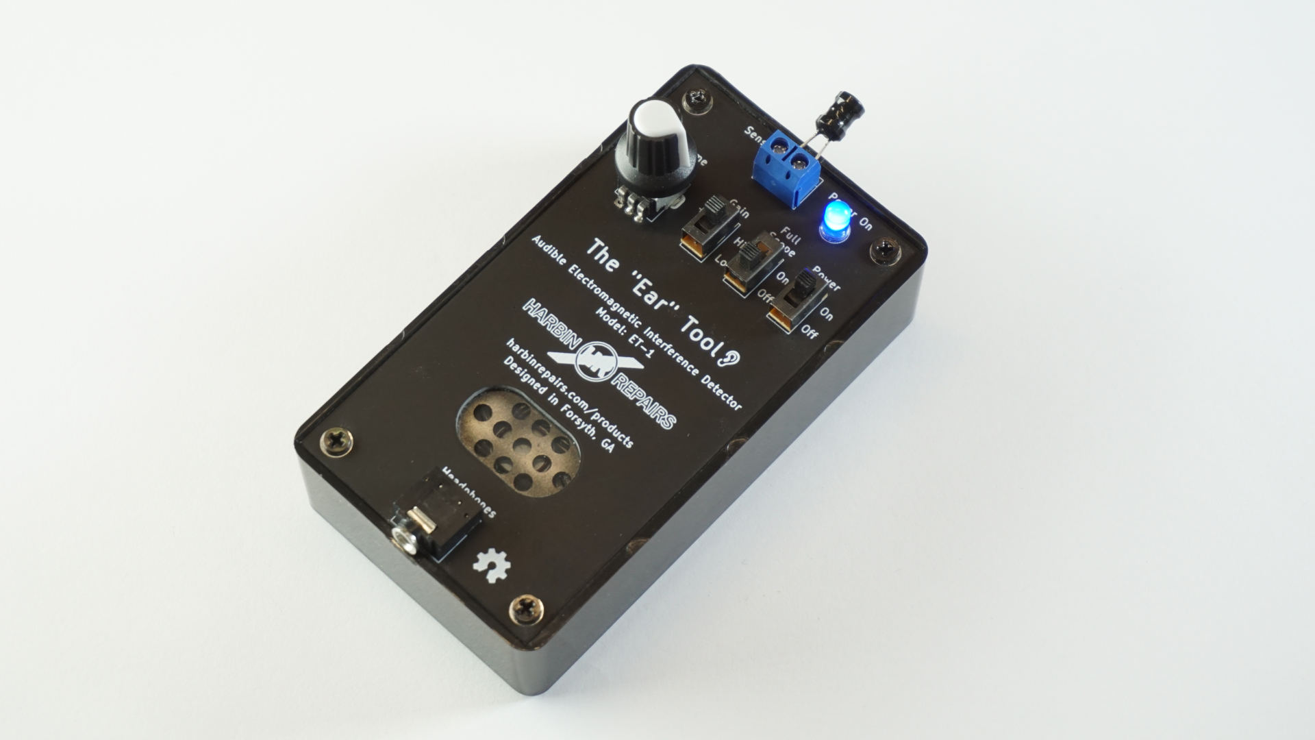
Audible Electromagnetic Interference Detector - Model ET-1
The Ear Tool is an open-source printed circuit board by HarbinRepairs, from the HarbinRepairs/The-Ear-Tool repository on GitHub, published under the GPL-3.0 licence. It is a 2-layer board of 57.7 × 107.7 mm with 23 parts on 18 nets, routed with 105 tracks and 1 via.
It is built around the LM386. Its parts include 3 connectors, 3 switches, 2 capacitors, 2 resistors and 1 IC.
Model: ET-1
Get this kit at our store: http://bit.ly/2TQ3Cbr Or on eBay: https://ebay.to/38sRZv4
Harbin Repairs 2020 Creative Commons Attribution ShareAlike 4.0 https://creativecommons.org/licenses/by-sa/4.0/
The Ear tool can be used to detect almost any electromagnetic interference coming from your electronics such as a power supply, transformer, CPU, microcontroller, wireless transmitter, relays, switches, speakers, transducers, transistors and more. At Harbin Repairs we use the Ear Tool to diagnose problems with computer motherboards, cellphones, and televisions by pointing the tool at different parts of a circuit board and listening to the high frequency pulsing coming from different components. For example, this can help us determine if a CPU or microcontroller is doing any processing or if it’s just sitting there burning up because there’s a short somewhere. It can also let us know if a cellphone or other device is turning on even if there’s no sign of life on the screen or lights. The tool can also be used to discover the different noises your electronics make when they are doing different things (e.g. standby mode vs. fully powered on). For the controls, the gain switch adjusts between high and low sensor gain and the full scope switch switch is used to help clear up some of the background noise. More examples are in the assembly guide video below.

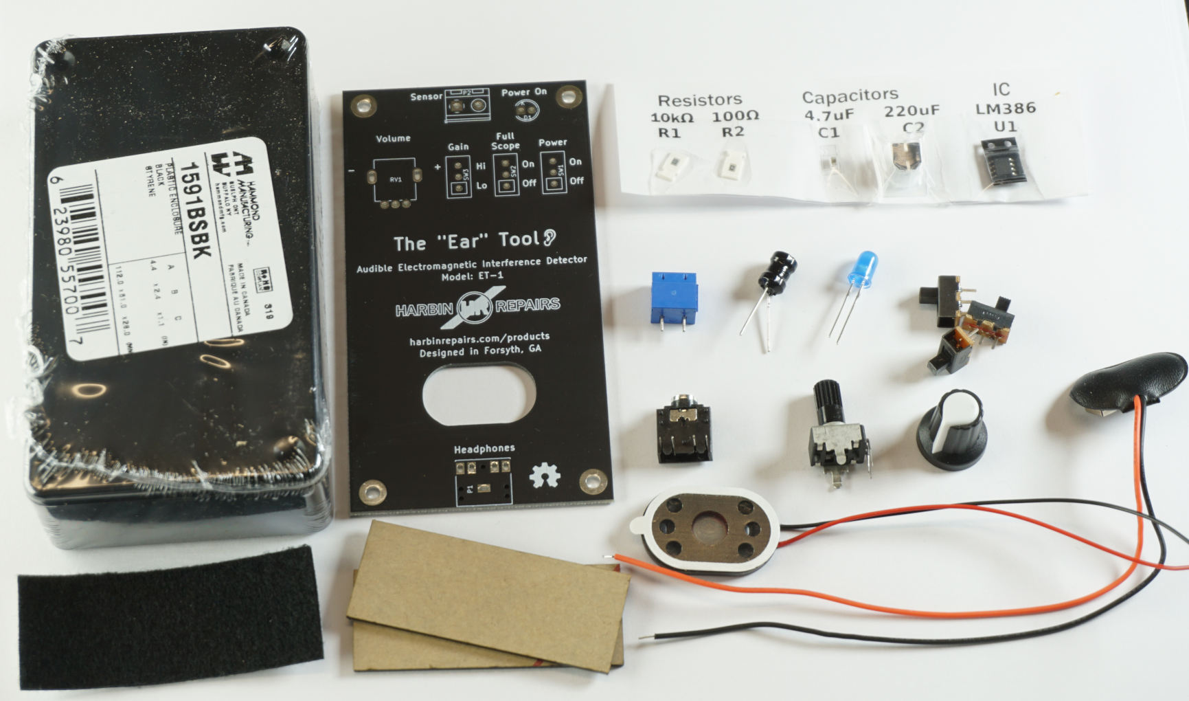
| Qty | Value | Footprint | References |
|---|---|---|---|
| 4 | MountingHole_3mm_Pad | Mounting_Holes:MountingHole_3mm_Pad | M1, M2, M3, M4 |
| 2 | LOGO | myFootprints:HR_LOGO_37.4x10.6mm | G1, G2 |
| 1 | 100 | Resistors_SMD:R_0805_HandSoldering | R2 |
| 1 | 10k | Resistors_SMD:R_0805_HandSoldering | R1 |
| 1 | 10k | myFootprints:POT_RV09_HORIZONTAL_WHO9 | RV1 |
| 1 | 220uF | Capacitors_SMD:CP_Elec_6.3x7.7 | C2 |
| 1 | 4.7uF | Capacitors_SMD:C_0805_HandSoldering | C1 |
| 1 | 9V Battery Clip | Oddities:NetTie-I_SMD | P3 |
| 1 | AUDIO-JACK-3F07-TRS | myFootprints:AUDIO-JACK-3F07-TRS | P1 |
| 1 | Full Scope Switch | myFootprints:SW_SPDT_3P_11.1mm_5.5mm | SW2 |
| 1 | Gain Switch | myFootprints:SW_SPDT_3P_11.1mm_5.5mm | SW3 |
| 1 | LED | LEDs:LED-5MM | D1 |
| 1 | LM386 | SMD_Packages:SOIC-8-N | U1 |
| 1 | LOGO | myFootprints:Ear_icon_4.2x4.2mm | G3 |
| 1 | Power Switch | myFootprints:SW_SPDT_3P_11.1mm_5.5mm | SW1 |
| 1 | Sensor Connector | TerminalBlock_RND:TerminalBlock_RND_205-00232_Pitch5.08mm | P2 |
| 1 | Speaker | Oddities:NetTie-I_SMD | LS1 |
The 21 most common of 23 parts.
profdc9/RFBitBanger
A QRP digital transceiver created from readily available parts for off-the-grid maintenance

mattybrad/drumkid
Version 4 was the first successful working design, with full code, schematics, Gerbers, etc available on GitHub.

leomil72/LM80C
A Z80-based homebrew computer withTMS9918, AY-3-8910, Z80 CTC, Z80 PIO, and Z80 SIO


oskitone/poly555
The POLY555 is a polyphonic, analog, square wave synth based on the 555 timer chip.

robfinch/Cores
Cores ===== RTF's Cores Use at your own risk. Welcome to my galaxy of cores. Contained in the directories are IP cores, source code for digital circuits.


It measures 57.7 × 107.7 mm and has 2 copper layers, 1.6 mm thick.
23 parts, built around the LM386. The full list of its parts is on this page, with links to each part's symbol and footprint where PCBKit's library has them.
From the HarbinRepairs/The-Ear-Tool repository on GitHub, at the commit this page was made from: the board is Kicad/The Ear Tool.kicad_pcb. PCBKit opens the board in the browser, with nothing to install.
Its repository publishes it under the GPL-3.0 licence: you may reuse it on that licence's terms (keep the author's notice, and for a copyleft licence share your changes alike).