2 layers116 × 55 mm
Reflow
Greentalinjo/GreenToaster
A reflow oven controller: RP2040, PT100 RTD, touchscreen profile editor, feed-forward + PID with automatic oven calibration, and a sealed 3D-printed mains enclosure.
8 parts

 Greentalinjo/GreenToaster
A reflow oven controller: RP2040, PT100 RTD, touchscreen profile editor, feed-forward + PID with automatic oven calibration, and a sealed 3D-printed mains enclosure.
Reflow low v is an open-source printed circuit board by Greentalinjo, from the Greentalinjo/GreenToaster repository on GitHub. It is a 2-layer board of 98 × 68.4 mm with 14 parts on 49 nets, routed with 125 tracks and 112 vias.
Its parts include 5 connectors, 5 switches, 2 ICs, 1 capacitor and 1 diode. It belongs with the RP2040 boards of this library.
A reflow oven controller that turns an ordinary toaster oven into a reflow oven for soldering surface-mount boards. An RP2040 reads a platinum RTD probe in the oven, follows a solder profile on a 3.5" touchscreen, and switches the oven's mains through a solid-state relay, all inside a sealed 3D-printed enclosure that sits between the wall socket and the oven.
Reflowing a board properly means following a temperature profile: preheat, soak, a short peak above the solder's melting point, then cooling. A toaster oven gets hot enough, but its thermostat can't follow a curve. GreenToaster replaces the thermostat. Plug the oven into GreenToaster, put the probe in the oven, pick a profile, and the controller drives the heater to track it.
[!WARNING] This project switches mains voltage (230 V AC). The power board, the SSR and the wiring in the tower carry lethal voltages. Only build it if you are competent with mains wiring, keep the tower closed when powered, and fit an independent thermal cutoff (a bimetal snap-disc or a thermal fuse) in series with the oven's heater. The firmware's safety layers can't help if the microcontroller itself fails. Never leave the oven unattended.
| At a glance | |
|---|---|
| Controller | WeAct RP2040-Pico (Raspberry Pi Pico-compatible) |
| Display | 3.5" 480 × 320 ILI9488 SPI touchscreen (LCDwiki MSP3520) |
| Sensor | PT100/PT1000 platinum RTD through a MAX31865 module |
| Output | SSR on the oven's mains, behind a five-switch hardware interlock |
| Control | feed-forward + PID, tuned automatically by a calibration run on your oven |
| Power | 230 V AC in, 5 V from an on-board HLK-10M05 supply |
| Profiles | 2 built in (Sn63Pb37 leaded, SAC305 lead-free) + 12 of your own |
| Firmware | C++ on the Arduino-Pico core, built with PlatformIO |
The design is split along the line every mains project should be: a mains side, sealed in the rear "tower" of the case, and a low-voltage side in the front "wedge", separated by a solid firewall with a single low-voltage pass-through.
flowchart LR
    subgraph mains["Mains side: the tower"]
        IN["C14 inlet<br/>230 V AC"] --> PB["Power board<br/>fuse, MOV, X-cap, choke<br/>HLK-10M05"]
        IN --> SSR["SSR<br/>on heatsink"]
        SSR --> OUT["Outlet<br/>the oven plugs in here"]
        FAN["60 mm fan<br/>cools the SSR heatsink"]
    end
    subgraph lv["Low-voltage side: the wedge"]
        CB["Controller board<br/>RP2040"]
        LCD["3.5in touchscreen"]
        SW["SW1..SW5<br/>interlock chain"]
        RTD["MAX31865<br/>RTD amplifier"]
    end
    PB -- "5 V" --> CB
    CB -- "5 V" --> FAN
    CB <--> LCD
    PROBE["PT100 probe<br/>in the oven"] --> RTD --> CB
    CB -- "SSR drive" --> SW -- "only if all 5 closed" --> SSR
Every 250 ms during a run:
That power becomes on/off time within a two-second window on the SSR, which switches the oven's mains. The SSR drive passes through five physical switches on the front panel. If any one is open, the oven cannot heat, whatever the firmware is doing.
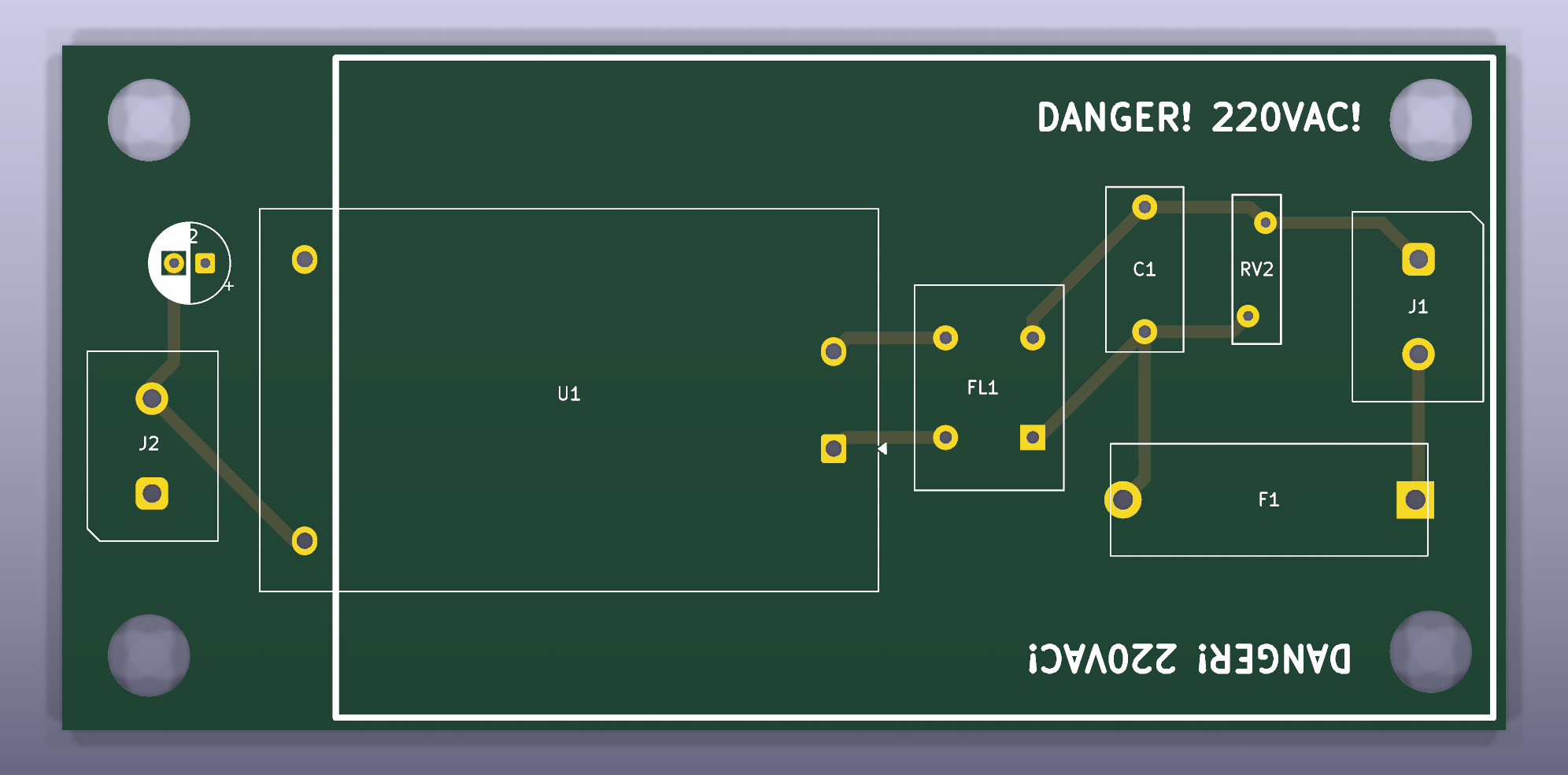
hardware/power-board)A small single-purpose mains board, 116 × 55 mm, that turns the wall supply into the controller's 5 V. In signal order:
| Part | Job |
|---|---|
| F1, 1 A fuse (5 × 20 mm) | in the line conductor, first thing after the input terminal |
| RV2, 10D561K varistor | clamps mains surges, behind the fuse so a failing MOV blows it |
| C1, 100 nF / 275 V X-capacitor | suppresses differential-mode noise |
| FL1, 10 mH common-mode choke | keeps the converter's switching noise off the mains |
| U1, HLK-10M05 | isolated AC/DC module, 5 V at up to 2 A (10 W) |
| C2, 220 µF | bulk capacitance on the 5 V output |
Mains comes in on J1 (pin 1 neutral, pin 2 line) and 5 V leaves on J2. Both are large 7.62 mm screw terminals. The board carries no logic at all: the SSR and the oven outlet are wired directly in the tower.
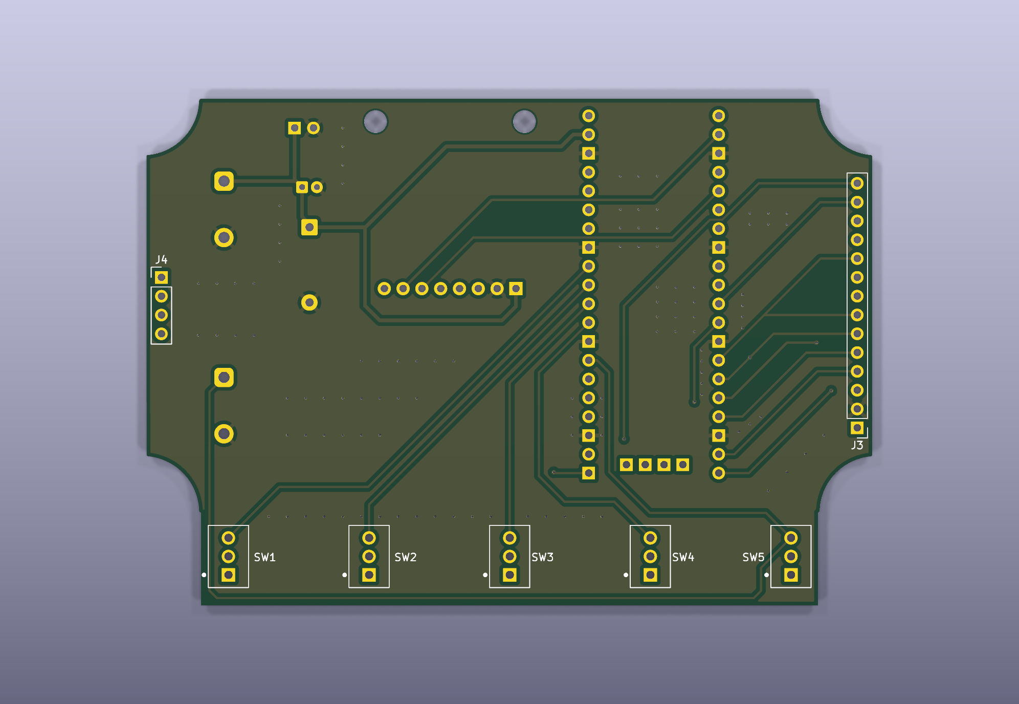
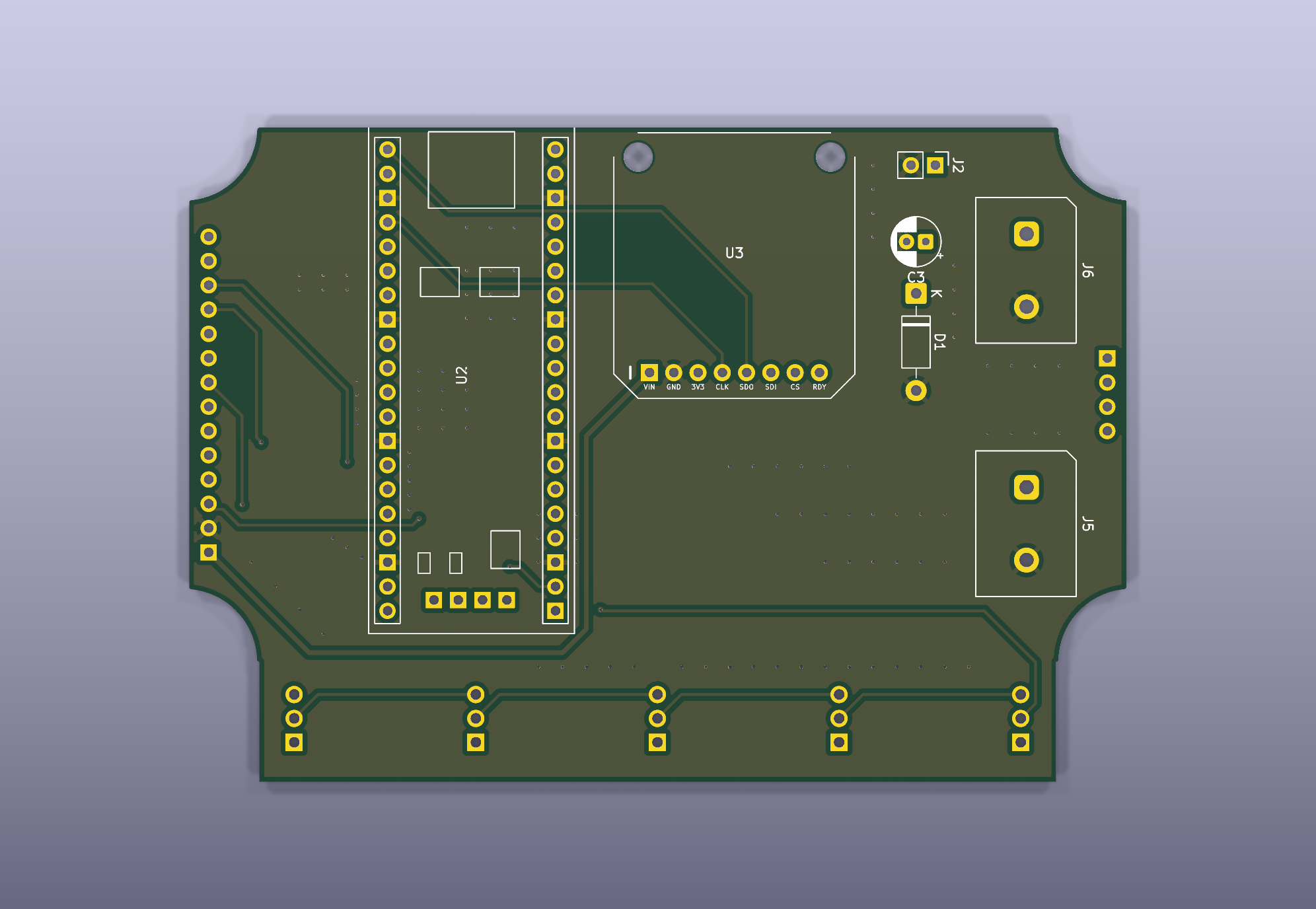
hardware/controller-board)A 98 × 68.5 mm carrier with ground poured on both sides. It holds the microcontroller and connects it to everything else:
| Ref | What | Connects to |
|---|---|---|
| U2 | WeAct RP2040-Pico | the brain |
| U3 | MAX31865 RTD module | the oven probe, on its own SPI bus (SPI0) |
| J3 | 14-pin header | the touchscreen and its XPT2046 touch controller, sharing SPI1 |
| SW1–SW5 | panel-mount SPDT toggles | the interlock chain (stage 4) |
| J5 | screw terminal | the SSR's control input |
| J6 | screw terminal | 5 V in, from the power board |
| J2 | 2-pin header | the heatsink fan, on the 5 V rail |
| D1, C3 | 1N5817, 100 µF | reverse-polarity clamp and bulk capacitance on the 5 V input |
| J4 | 4-pin header | not connected electrically |
5 V from J6 feeds the Pico's VSYS. The WeAct module's own USB connector also
feeds VSYS through its on-board diode, so USB alone powers the board for
flashing. The display is write-only: its data-out pin isn't connected, so only
the touch controller talks back on SPI1. The full pin map is in
firmware/include/board_pins.h.
firmware/src/sensor.cpp)The probe is a platinum RTD read by a MAX31865 in continuous conversion mode. The chip converts on its own, and the firmware just collects a sample every 250 ms, so reading the oven never stalls the touchscreen. Resistance becomes temperature through the Callendar–Van Dusen equation for IEC 60751 platinum sensors.
Faults are decoded rather than hidden. NO SENSOR, RTD OPEN, RTD SHORT,
RTD OV/UV or RTD RANGE replaces the reading on screen. Each detected fault
is cleared and fault detection re-armed, so a passing glitch can't latch.
firmware/src/interlock.cpp)The SSR is driven from GPIO 16 through all five panel switches in series:
GP16 → SW1 → SW2 → SW3 → SW4 → SW5 → J5 (SSR+)
          ↓      ↓      ↓      ↓      ↓
        GP28   GP27   GP26   GP22   GP21     (taps, read by the firmware)
Opening any switch physically cuts the SSR drive. The taps between the switches, held low by the RP2040's internal pull-downs, let the firmware see how far the chain is closed. It counts closed switches from SW1 onwards, so a floating input can never report more than are really closed.
Reading the taps needs GP16 high, and GP16 high with all five closed is the heater on. So while arming, the firmware senses with 50 µs pulses, at most 50 per second, which is far too little to heat anything. During a run it reads the taps for free during the SSR's on-time.
firmware/src/control.cpp)The controller is feed-forward plus PID:
duty = feed_forward(setpoint) + PID(setpoint − measured)The SSR is time-proportional over a 2 s window, which is 100 mains half-cycles at 50 Hz, so the duty resolution is 1 %.
Instead of hand-tuning, the controller measures your oven in an automatic dry run, with the oven empty and cold (it refuses to start above 50 °C):
| Phase | Heater | Runs until | Measures |
|---|---|---|---|
| 1 baseline | off | 15 s | ambient temperature |
| 2 step response | 100 % | 200 °C | dead time and peak heating rate |
| 3 relay autotune | 70 % / off around 180 °C | 4 clean oscillations | ultimate gain Ku, period Pu, and the power needed to hold 180 °C |
| 4 cooling | off | down to 150 °C | passive cooling rate |
Phase 3 is the Åström–Hägglund relay method, which characterises the oven at
reflow temperature. The PID gains use the no-overshoot rule (Kp = 0.2·Ku,
Ti = 0.5·Pu, Td = 0.33·Pu), because overshoot on a reflow profile is what
damages boards. Each phase has a timeout, so a fault can't leave it running.
At the end, the screen shows an Oven characterised card: the oven's gain,
heating and cooling rates, Ku/Pu, and the resulting PID gains. The model
is saved to flash (/oven.bin) and survives reflashing. Start Reflow is
refused until a dry run has succeeded.
firmware/src/screens_*.cpp)Home ──┬── Profiles ─── Profile view ──── Arming ──── Run (live graph)
│ (graph, Start Reflow / Dry Run)
└── New Profile ─── Section editorA four-button rail down the right edge (UP, DOWN, SAVE, BACK) keeps the same meaning on every screen. Held buttons auto-repeat after 450 ms, so stepping a temperature up doesn't take dozens of taps. The case's bezel covers the panel's left edge, so every screen is laid out clear of it.
The hardware interlock: the SSR cannot be driven unless all five switches are closed.
The independent thermal cutoff you fit in series with the heater (see the warning above).
Software aborts:
A run also won't start if the sensor is faulty, the oven is already over 280 °C, or another run is in progress.
A hardware watchdog (8 s), armed as soon as any run is armed and kept until the next reboot. If the firmware hangs, the reset drops every pin to high impedance, which the SSR reads as off.
firmware/platformio.ini| Build flag | Default | Set it to |
|---|---|---|
MAX_RREF_OHMS | 430.0f | the module's reference resistor: 4300 marking = 430 Ω (PT100), 4301 = 4.3 kΩ (PT1000) |
MAX_RNOMINAL_OHMS | 100.0f | the probe's resistance at 0 °C: 100 for PT100, 1000 for PT1000 |
MAX_WIRES | 3 | 2, 3 or 4, matching the solder jumpers on the module |
MAX_FILTER_50HZ | 1 | 1 for 50 Hz mains, 0 for 60 Hz |
Built in, and can't be deleted:
| Profile | Sections (target °C / seconds to reach it) |
|---|---|
| Sn63Pb37 leaded | 150 / 90 → 180 / 60 → 235 / 45 → 235 / 20 → 50 / 100 |
| SAC305 lead-free | 150 / 90 → 200 / 90 → 249 / 45 → 249 / 20 → 50 / 110 |
Your own: up to 12 profiles of up to 16 sections, built on the touchscreen. A section is a ramp: a target temperature (up to 300 °C, in 5 °C steps) and the time to reach it from the previous section (up to 900 s, in 5 s steps). A hold is a section that repeats the previous temperature. Profiles are stored in flash, written through a temporary file so a power cut can't corrupt them.
| Key | Does |
|---|---|
t | raw RTD dump: ADC code, resistance and temperature. A PT100 at 25 °C reads about 109.7 Ω |
m | prints the calibrated oven model and PID gains |
i | shows how many interlock switches are closed |
T | SSR self test: 25 % duty (0.5 s on, 1.5 s off) once the interlock closes, for up to 60 s. It stops early if the oven warms by 25 °C or reaches 80 °C |
x | aborts a run |
c | touch calibration (see below) |
While the oven is being driven, the board also prints one CSV telemetry line
per second (R,t_s,mode,phase,temp_c,set_c,duty_pct,armed), which
firmware/scripts/log_run.py captures to a log file.
| Where | What |
|---|---|
src/main.cpp, gTouchCalibration | touch calibration. Send c, take the display out of the case first so you can reach the corner targets, then paste the printed values here |
platformio.ini, SPI_FREQUENCY | the display's SPI clock (27 MHz). Lower it if the image corrupts |
platformio.ini, board_build.filesystem_size | the 4 MB flash partition for profiles and the oven model. Changing it orphans what's already stored |
src/control.cpp | the safety limits, the SSR window and the dry-run phases. Change them only if you understand them |
Both are 2-layer boards made with KiCad 10. Open the .kicad_pro in each
folder under hardware/ and plot gerbers and drill files. Each project carries
copies of every symbol and footprint it uses, so the boards open and plot
without any extra libraries. Schematic PDFs are in docs/.
| Power board | Controller board | ||
|---|---|---|---|
| U1 | HLK-10M05 | U2 | WeAct RP2040-Pico |
| F1 | 1 A fuse, 5 × 20 mm, with holder | U3 | MAX31865 RTD module (8-pin) |
| RV2 | 10D561K varistor | J3 | 1 × 14 header, to the MSP3520 display |
| C1 | 100 nF 275 V X2, 10 mm pitch | SW1–SW5 | SMTS-102 SPDT toggle switches |
| FL1 | 10 mH common-mode choke, UU9.8 | J5, J6 | 7.62 mm 2-way screw terminals |
| C2 | 220 µF, 6.3 mm radial | J2, J4 | 1 × 2 and 1 × 4 headers |
| J1, J2 | 7.62 mm 2-way screw terminals | D1, C3 | 1N5817, 100 µF |
Also needed: an SSR with a heatsink, a 60 mm 5 V fan, a C14 inlet, an outlet for the oven, a PT100 probe (3-wire to match the default build), mains-rated wire, and the thermal cutoff.
cd firmware
pio run                 # build
pio run -t upload       # flash
pio device monitor      # serial console, 115200 baud
Uploading needs no driver. scripts/upload_uf2.py resets the board into
its bootloader and copies the firmware onto the RPI-RP2 drive, so you don't
need picotool, Zadig or the BOOT button.
t at room temperature. If it's off, fix the RTD
build flags.i, closing the switches one at a time.T.Five printable parts, in case/:
| File | Part |
|---|---|
reflow_tower.stl | the sealed mains tower: the power board, the SSR on its heatsink, the fan, the C14 inlet and the oven outlet, with the firewall at its front |
reflow_lid.stl | the tower's vented lid |
reflow_wedge.stl | the slanted front wedge: the low-voltage side, holding the controller board behind the panel |
reflow_panel.stl | the faceplate, with the display window and the five switch holes. The display screws to it |
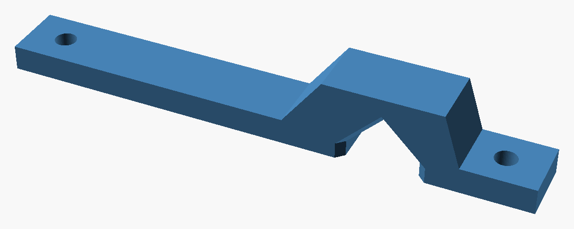
reflow_fanbar.stl | the fan bar that mounts the cooling fan |
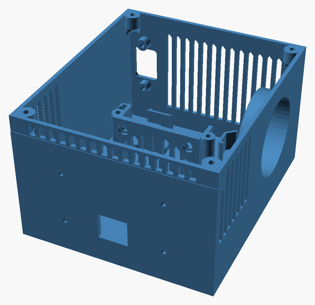
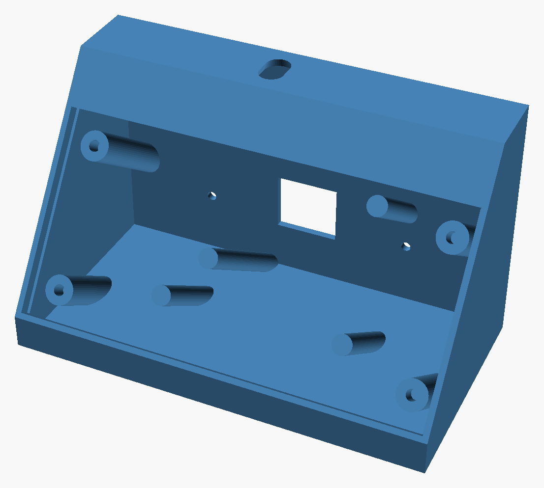
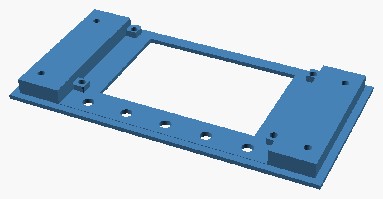
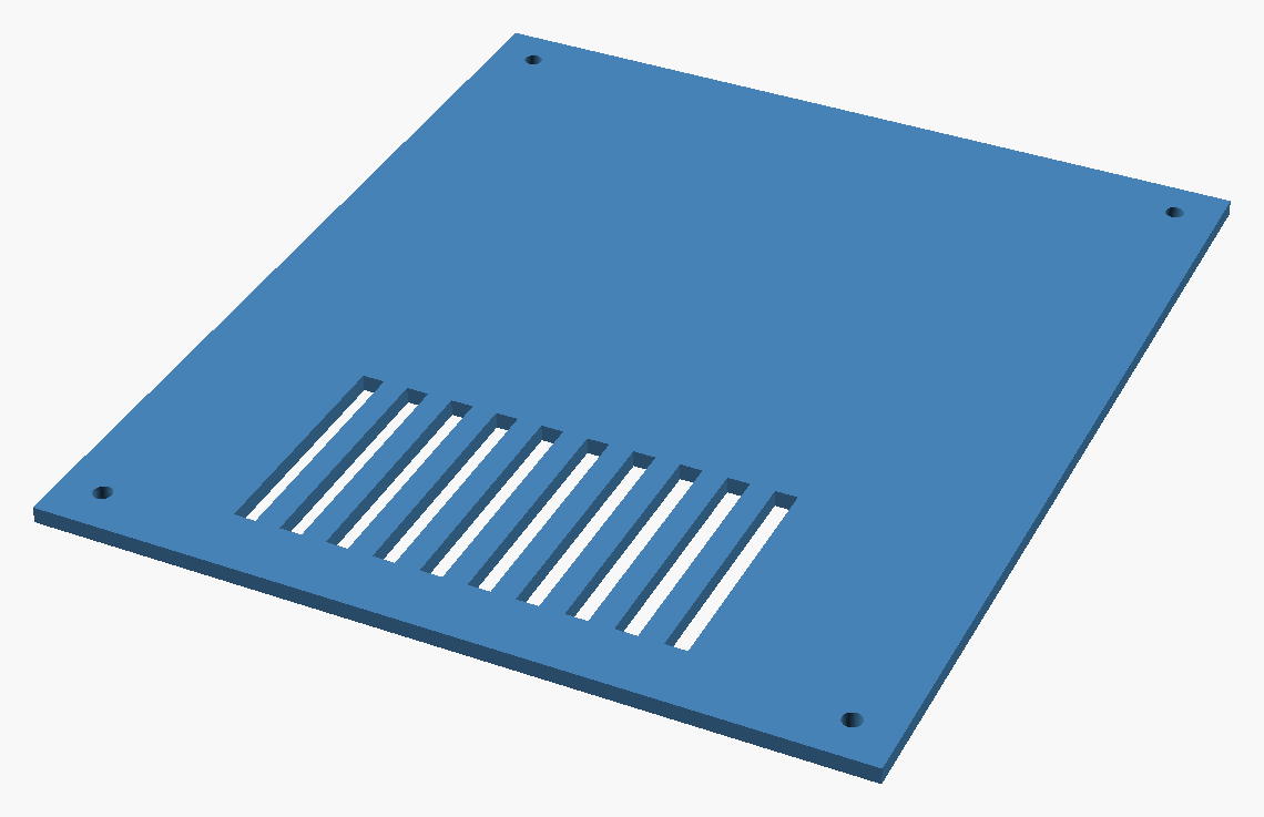
The mains side and the low-voltage side never share an open space. The only link between them is a single low-voltage pass-through in the firewall.
hardware/
  power-board/          KiCad project: the 230 V AC to 5 V board
  controller-board/     KiCad project: the RP2040 controller board
firmware/               PlatformIO project
  platformio.ini          build settings, display and RTD configuration
  include/, src/          the firmware (pin map in include/board_pins.h)
  scripts/                UF2 uploader, run logger, interlock watcher, layout check
case/                   STL files for the five printed parts
docs/
  power-board-schematic.pdf
  controller-board-schematic.pdf
images/ renders used in this README| Qty | Value | Footprint | References |
|---|---|---|---|
| 5 | SW_SPDT | smts-102:SW_Toggle_SPDT_SMTS-102 | SW1, SW2, SW3, SW4, SW5 |
| 1 | 100uF | Capacitor_THT:CP_Radial_D5.0mm_P2.00mm | C3 |
| 1 | 1N5817 | Diode_THT:D_DO-41_SOD81_P10.16mm_Horizontal | D1 |
| 1 | Conn_01x04 | Connector_PinHeader_2.54mm:PinHeader_1x04_P2.54mm_Vertical | J4 |
| 1 | Conn_01x14 | Connector_PinHeader_2.54mm:PinHeader_1x14_P2.54mm_Vertical | J3 |
| 1 | Fan Connector | Connector_PinHeader_2.54mm:PinHeader_1x02_P2.54mm_Vertical | J2 |
| 1 | MAX31865_RTD_Module | 31865:MAX31865_RTD_Module_2 | U3 |
| 1 | Power Connector | big_terminal:TerminalBlock_E-Simpo_128_1x02_P7.62mm | J6 |
| 1 | SSR Connector | big_terminal:TerminalBlock_E-Simpo_128_1x02_P7.62mm | J5 |
| 1 | WeAct-RP2040-Pico | WeAct-RP2040-Pico:WeAct-RP2040-Pico | U2 |
Greentalinjo/GreenToaster
A reflow oven controller: RP2040, PT100 RTD, touchscreen profile editor, feed-forward + PID with automatic oven calibration, and a sealed 3D-printed mains enclosure.

google/mozc-devices
Circuit diagrams and firmware source code for Gboard DIY keyboards


hackclub/OnBoard
💡 Join 1,000 teenagers and make your first PCB with a $100 grant!


Twotoz/C5VRX
Ultra-minimal, zero-CPU 5.8 GHz analog FPV video receiver using ESP32-C5 Wi-Fi 6 PHY MODEM_DIAG, BitScrambler WBFM demodulation & resistor DAC CVBS


It measures 98 × 68.4 mm and has 2 copper layers, 1.6 mm thick.
14 parts. The full list of its parts is on this page, with links to each part's symbol and footprint where PCBKit's library has them.
From the Greentalinjo/GreenToaster repository on GitHub, at the commit this page was made from: the board is hardware/controller-board/reflow_low_v.kicad_pcb and its schematic hardware/controller-board/reflow_low_v.kicad_sch. PCBKit opens the board in the browser, with nothing to install.
Its repository states no licence, so its author keeps all rights: ask Greentalinjo before reusing the design.