2 layers42.4 × 52.5 mm
Monitorio
GoldbergLab/Monitorio
Hardware and software for precisely syncing computer monitor display output to other data streams
21 parts
 GoldbergLab/Monitorio
Hardware and software for precisely syncing computer monitor display output to other data streams
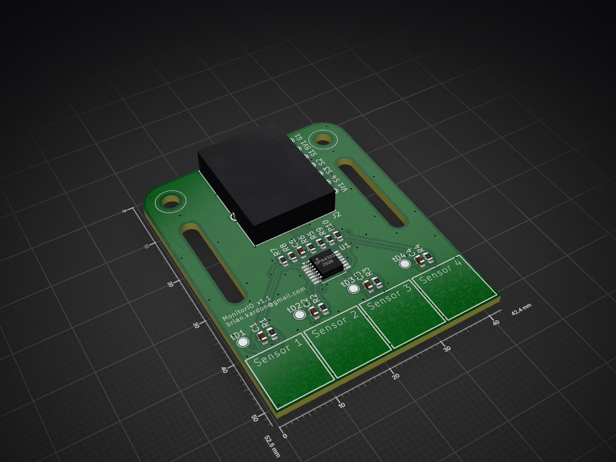
Monitorio v1.1 is an open-source printed circuit board by GoldbergLab, from the GoldbergLab/Monitorio repository on GitHub. It is a 2-layer board of 42.4 × 52.5 mm with 32 parts on 15 nets, routed with 344 tracks and 75 vias.
It is built around the OPA4323IPW and MTJ-88TX1-FSD-PGB. Its parts include 10 resistors, 5 capacitors, 4 diodes, 1 IC and 1 connector.

Hardware + software for sub-frame-accurate synchronization between a displayed video and an external recording, using on-screen photodiode sync tags.
The video tagging script overlays a small array of black/white "bit circles" onto each frame of a video; the bits encode the frame number in reflected-binary Gray code. A small PCB of photodiodes (Monitorio) is mounted on the display so each photodiode covers one bit position. The photodiodes' analog outputs go into an NI-DAQmx data acquisition card, which records them alongside whatever else the experiment is sampling. Decoding that DAQ trace recovers, for each DAQ sample, which video frame was on screen at that moment.
You only need the Monitorio PCB if you want a turnkey assembly. The software side works with any photodiode + amplifier hardware that produces an analog voltage proportional to local screen illumination, fast enough to settle within one video frame. A breadboard build with discrete photodiodes and a single quad op-amp is sufficient; the calibration tool will locate them automatically wherever you stick them on the screen.
Hardware/
  Monitorio v1.0/          KiCad project + Gerbers for the v1.0 PCB
  Monitorio_v1.1/          v1.1 (4 photodiodes, OPA4323 quad TIA, RJ45 out)
Monitorio.bat              Double-click launcher for the GUI (Windows)
Source/
  monitorio_gui.py         GUI entry point (see "GUI" below)
  gui/                     GUI implementation (PySide6)
    library.py             folder scan, sidecar parsing, ffprobe (no Qt)
    main_window.py         folder browser + video details window
  add_video_sync_tags.py   CLI: tag a video with sync circles
  decode_sync_tags.py      Python module: recover video frame # per DAQ sample
  decodeSyncTags.m         MATLAB wrapper around decode_sync_tags.py
  setupMonitorioPython.m   MATLAB helper: pyenv setup against the repo venv
  calibration/             Calibration pipeline (NI-DAQmx + pygame)
    daq.py                 NI-DAQmx wrapper
    display.py             pygame-ce fullscreen drawing primitives
    procedure.py           baseline / localize / refine / rise-time / crosstalk
    plot.py                matplotlib visualization of calibration results
    gray.py                reflected-binary Gray code encode/decode
    io.py                  pipeline cache (.npz) so reruns skip the slow steps
    scripts/
      calibrate.py         CLI: full calibration end-to-end -> JSON output
      smoke_test_*.py      individual stage tests for development
decode_stream.py CLI: batch-decode every playback in a sessionThe Monitorio PCB (see Hardware/Monitorio_v1.1/) carries four surface-
mount photodiodes (D1-D4), an OPA4323 quad op-amp configured as four
transimpedance amplifiers, and an RJ45 output jack. Each PD's amplified
voltage is one channel; the cable carries all four plus ground/shield to
a breakout into the DAQ. Run on a single 5 V supply, so signals are
0-5 V (typically ~50% dynamic range with the default photodiode
sensitivity and gain).
Pieces of the PCB design files:
*.kicad_sch, *.kicad_pcb -- KiCad schematic and board.CAM/ -- Gerbers and drill file for fab.Photodiode Amplifier Reference Circuit.pdf -- the TI app note the
TIA topology is taken from.The software does not know or care about the PCB. Channel layout is detected from photodiode response during calibration, and any other analog source that meets the requirements below can be substituted.
If you're not using the Monitorio PCB, your replacement must:
scale argument. Channels for calibration can be
single-ended (RSE/NRSE) or differential (DIFF/PSEUDO_DIFF); the
calibration script accepts a --terminal-config flag. A loader
for Intan RHD recordings is included
(Source/loaders/rhd.py); other formats are bring-your-own.Driver and OS-level tools (install separately, not via pip):
nidaqmx to talk to any DAQ device. Windows builds are
the most-tested target; Linux builds are also available from NI.ffprobe) -- must be on PATH. The video tagging
script shells out to ffmpeg for decoding/encoding; the decoder uses
ffprobe to read fps and frame count from the tagged video; the
playback script also probes videos with ffprobe.Source/playback/play_random.py). The python-vlc Python package
is just the bindings; the actual VLC binary needs to be installed
separately. Skip this if you don't use the playback driver. Note
that the VLC folder that contains libvlc.dll (typically the same
one that contains vlc.exe) must be on the system path, and the
bitness of VLC (32 vs 64) must match the bitness of python
(probably 64 bit).Python packages (install with pip install -r requirements.txt inside
a virtualenv):
pygame-ce>=2.5 -- fullscreen rendering for calibration patterns
and the random-playback driver.numpy>=1.26nidaqmx>=1.0 -- requires the NI driver above; only used by
calibration.matplotlib>=3.8 -- inspection plots that pop up at the end of
calibration; harmless if unused elsewhere.python-vlc>=3.0 -- bindings for the random-playback driver.
Skip / uninstall if you don't run play_random.py.PySide6-Essentials>=6.8 -- Qt bindings for the GUI. Skip if you
only use the command-line scripts.For running the test suite, also: pip install -r requirements-dev.txt
(currently just pytest).
   +-----------+    +-------+    +--------+    +--------+    +--------+
   | calibrate | -> |  tag  | -> | play / | -> | decode | -> |  use   |
   | (one-off) |    | video |    | record |    |  per   |    | frame  |
   |           |    |       |    |        |    | sample |    |  -> t  |
   +-----------+    +-------+    +--------+    +--------+    +--------+
        |               ^   ^             |        ^               |
        v               |   |             v        |               v
   calibration ---------+   +---- tagged video --->|       (your analysis)
   JSON                                            |
                                                   |
DAQ samples (numpy array, any source) ----------+Source/playback/play_random.py automates
the display side (random video selection + exponential inter-video
gaps) for animal-experiment workflows.Source/decode_sync_tags.py: pass
in the recorded (n_channels, n_samples) numpy array, the tagged
video path, and the calibration JSON. Get back a table of
(frame_number, sample_index) rows. The decoder reads the
tagger's <output_video>.tags.json sidecar automatically for the
sync-bit setting and channel-to-bit assignment. A loader for
Intan RHD recordings is included in Source/loaders/rhd.py;
other formats: load samples however you like.# One-off, after wiring up the PD board and pointing it at the display.
# Runs the full calibration interactively (instruction screens + plots,
# asks before saving). Output: calibration_<timestamp>.json
venv/Scripts/python Source/calibration/scripts/calibrate.py
# Tag a video against an existing calibration JSON.
venv/Scripts/python Source/add_video_sync_tags.py \
in.mp4 out.mp4 \
--calibration-file calibration_20260417-162539.json
# Or do both in one step (calibrates first, then tags using its JSON):
venv/Scripts/python Source/add_video_sync_tags.py \
in.mp4 out.mp4 --calibrate
# Manual override -- skip calibration entirely if you have known
# good positions for the rig:
venv/Scripts/python Source/add_video_sync_tags.py \
in.mp4 out.mp4 \
--bit-xs 75,140,205,270 --bit-ys 1850 \
--bit-radius 15 --background-radius 25
# Run a random-playback session (drives the rig during recording):
venv/Scripts/python Source/playback/play_random.py CONFIG.toml
# (See Source/playback/example_config.toml for the config format.)After recording, decode in Python:
from decode_sync_tags import decode_sync_tags
from loaders.rhd import load_rhd_board_adc   # Intan; or roll your own loader

bundle = load_rhd_board_adc(["recording.rhd", "recording_2.rhd"])
result = decode_sync_tags(
    bundle.samples[2:5],         # the 3 channels carrying the PD signals
    sample_rate=bundle.sample_rate,
    video_path="exp01_tagged.mp4",
    calibration_path="cal.json",
    output_path="frame_table.csv",
)
# result.frame_table[:, 0] = frame numbers; result.frame_table[:, 1] = sample indicesA desktop front end over the command-line scripts, for browsing a
folder of videos and seeing which are tagged and how. Double-click
Monitorio.bat in the repo root, or run:
venv/Scripts/python Source/monitorio_gui.py [FOLDER]Pick a folder (optionally including its subfolders) to list its
videos. A video counts as tagged if the tagger's sidecar
(<video>.tags.json) sits next to it. Selecting a video shows its
frame size, frame rate, frame count, duration and codec; for a tagged
video it also shows the tagging scheme (sync bit, number of
frame-number bits, guard frames), the screen it was tagged for, the
on-screen tag positions, and the source video and calibration file it
was made from -- flagging either if it can no longer be found. Tag
positions are read back from the calibration file, so they're only
shown while that file is still reachable at the path recorded at
tagging time.
The GUI works on any machine with ffmpeg on PATH; it doesn't need
the DAQ driver, VLC, or the rig. It is being built in stages: tagging,
calibration, a frame-by-frame viewer and a hardware panel are not in
it yet -- use the command-line scripts below for those.
calibrate.py referenceRuns all of the following, in order, and writes the result to a single JSON file:
After all measurements complete, three matplotlib figures pop up (spatial response, temporal response, crosstalk heatmap) for visual sanity check. The script then asks whether to save the JSON.
The JSON contains: monitor index/resolution, DAQ device + product type
(x_px, y_px, bit_radius_px, background_radius_px, baseline_dark_v, baseline_bright_v, dynamic_range_v, rise_duration_s, fall_duration_s, ...). Plus the full
crosstalk matrix.Common flags:
--display N -- pick which monitor (default 0).--device NAME -- pick which DAQ device, e.g. Dev1.--terminal-config {RSE,DIFF,NRSE,PSEUDO_DIFF} -- AI terminal
configuration. RSE is the default. In DIFF/PSEUDO_DIFF the script
automatically restricts itself to the half of physical channels that
the device exposes as differential positive inputs.--cache PATH -- cache the slow baselines + coarse + fine
measurements (~1 min) so a re-run picks up where the last left off.
Default is calibration_cache.npz in CWD. Pass --force to ignore
any existing cache.--no-plot, --no-confirm -- non-interactive batch mode.--crosstalk-threshold PCT -- pass/fail threshold (default 5%).add_video_sync_tags.py referenceReads video_in, writes video_out with a Gray-coded sync-tag overlay
at every frame. Audio (if present) is copied through unchanged.
Parameter resolution order (per parameter, top wins):
--bit-xs, --bit-radius, etc.)--calibration-file or --calibrate).Frame numbers are 1-indexed. With sync-bit mode (the default,
--sync-bit), the first PD is reserved as an always-on indicator
and the remaining N-1 PDs carry an N-1-bit Gray-coded frame counter
that cycles every 2**(N-1) frames. The Gray code preserves the
single-bit-change-per-step property across the wrap edge; the
decoder disambiguates which cycle each sample belongs to using sample
timing and frame-rate info from the tagged video. With --no-sync-bit,
all N PDs carry the counter (cycle 2**N), but frames at every
multiple of the cycle Gray-encode to all-bits-off, which is
indistinguishable from "video off" in the recording -- so the
default --sync-bit is recommended unless you really need the extra
bit of cycle length.
Selected flags:
--calibration-file PATH -- use a saved calibration JSON.--calibrate -- run calibrate.py first and use its output, all in
one command. Forwards --display, --device, --cache, --force,
--terminal-config to the subprocess.--bit-xs A,B,C, --bit-ys A,B,C, --bit-radius N,
--background-radius N -- manual overrides for any of the calibrated
values. All are in screen pixel coords (the same coord system the
calibration JSON uses), not video-frame coords.--leading-guard-frames N -- prepend N untagged black frames to the
output (default 5). Most video players silently skip 1–3 frames at
the start of playback; the guards absorb those skips so real source
frames still play cleanly. Guards have sync OFF, so the decoder's
segment detection ignores them entirely -- decoded frame N maps
directly to source video frame N regardless of how many guards the
player consumed (up to N). Set to 0 to disable.--sync-bit / --no-sync-bit -- whether to reserve the first PD as
an always-on "video active" indicator. Enabled by default. When
on, PD index 0 in the calibration JSON (= the lowest-numbered live
AI channel, by physical pin order) is lit on every video frame, and
the remaining n-1 PDs Gray-encode the frame number. This lets the
decoder cleanly distinguish "video off" (sync dark) from any frame
state (sync lit) -- without it, frame numbers at every multiple of
2**n_bits encode to all-dark and look identical to "off." Cost: the
cycle drops by 2x (16 -> 8 with 4 PDs), so the decoder has to
disambiguate cycles from timing more often. The script prints the
sync/frame-bit channel assignment at startup so a decoder author can
confirm it.--pad-for-unambiguous-end / --no-pad-for-unambiguous-end --
only relevant in --no-sync-bit mode. If the input video's frame
count is an exact multiple of the cycle length, the very last
frame Gray-encodes to all-zeros and would be indistinguishable from
"video off." With this flag (default on), the tagger appends a
single extra black-content frame so the final tag pattern is
unambiguous. No-op in sync-bit mode (the issue can't arise there).--screen-size WxH -- screen pixel dimensions of the display the PD
board is mounted on, e.g. 2400x1600. Required unless
--calibration-file is given (then read from the JSON's
monitor.width/height). The output video is rendered at whatever size
preserves the screen aspect ratio with minimal padding around the
input (no upscaling, no cropping); tag positions and radii are scaled
by output_w / screen_w so they land at the correct screen pixels
when the output is shown full-screen on this display. The script
errors out if the input is larger than the screen in either dimension
(cropping would lose content), and warns if the scaled tag radius
drops below ~3 px (likely too small to read reliably -- use a larger
input video).--codec NAME -- ffmpeg encoder. Defaults to libx264 (CPU; always
works). On a machine with an NVIDIA GPU and an ffmpeg build linked
against the NVIDIA SDK, --codec h264_nvenc (or hevc_nvenc) is
typically 5-10x faster. The script does a build-level check at
startup and errors out if the encoder isn't compiled in; runtime
failures (e.g. ffmpeg has the encoder but the GPU isn't supported)
surface as an ffmpeg error during the encode -- if that happens,
fall back to the default.--preset NAME -- encoder preset. Defaults are codec-dependent:
veryfast for libx264, p4 (medium) for NVENC. Pass any preset
string the chosen encoder accepts.--quality N -- visual-quality knob; lower = higher quality, larger
file. Mapped to -crf for libx264 and -cq for NVENC. Default 18
is perceptually lossless on both.--progress -- per-frame progress.decode_sync_tags.py referenceAfter recording the photodiode signals on a DAQ alongside whatever else
the experiment is sampling, Source/decode_sync_tags.py recovers the mapping
between video frame number and DAQ sample index.
The repo deliberately doesn't include code for parsing your specific DAQ's file format -- load the samples into a numpy array however you like, then call:
from decode_sync_tags import decode_sync_tags

result = decode_sync_tags(
    samples,                           # (n_channels, n_samples) array
    sample_rate=50_000,                # Hz
    video_path="exp01_tagged.mp4",     # the tagger's output
    calibration_path="cal.json",       # the calibration JSON
    scale="intan_aux",                 # samples are Intan ADC steps
                                       #   ('volts', 'intan_aux',
                                       #   'intan_supply', etc., or a
                                       #   numeric multiplier)
    output_path="exp01_frames.csv",    # CSV table to write
    metadata="2026-04-30 rig A trial 7",
)
# result.frame_table is an (n_frames, 2) int64 array of
#   (frame_number, sample_index) rows.
The tagger writes a sidecar <output_video>.tags.json next to its
output that records the sync-bit setting and channel-to-bit assignment;
the decoder reads it automatically. Pass sync_bit_override=True/False
to force a value (useful if the sidecar is missing or wrong).
The decoder assumes the recording contains exactly one complete
video playback bracketed by "video off" padding on both sides. It
raises RuntimeError for fundamental problems:
--no-sync-bit mode). Recording probably has no video at all, the
channel order doesn't match calibration, or the scale factor
produced near-constant voltages.Softer issues land in result.warnings_ (and the CSV's # warning:
header lines):
minor ≤ 5, noteworthy > 5).Specific case worth flagging in --no-sync-bit mode: if the video's
total frame count is an exact multiple of 2**n_pds (i.e. the cycle
length), the very last frame Gray-encodes to all zeros and is
indistinguishable from the post-video "off" period. The tagger handles
this by default by appending a single black-content frame so the output
isn't an exact cycle multiple (--no-pad-for-unambiguous-end opts
out); the decoder also has a safety-net that detects the case if it
slips through, synthesizes the missing last frame at
last_real_sample + sample_rate/fps, and emits a warning suggesting
--sync-bit to remove the ambiguity. With --sync-bit on (the
default) the issue can't arise -- the sync PD is lit on every video
frame.
Pass verbose=1 for a one-line summary of decoder decisions
(input shape, sync-bit source, segment bounds, decoded count) printed
to stderr; verbose=2 adds per-channel thresholds, SNR values,
detected segments, and per-transition unwrap accounting. Useful when a
real-rig recording isn't decoding the way you expect.
The internal bimodal threshold is found per channel via Otsu's method
on the recording itself, with the calibration JSON's
baseline_dark_v / baseline_bright_v used only as a sanity check.
This makes the decoder unit-agnostic given the right scale: NI DAQ
records in volts (scale="volts" or 1.0); Intan auxiliary input
channels record raw ADC steps that convert to volts at
0.0000374 V/step (scale="intan_aux"). The SCALE_PRESETS dict in
decode_sync_tags.py lists the available shorthand names. Also be aware that
the Intan aux input ranges only ~0 to 2.45 V -- verify the PD signal
doesn't clip at the top of that range.
The CSV output has a #-prefixed header carrying the source video
path, calibration path, sample rate, fps, sync-bit setting, cycle,
per-channel detected thresholds, segment bounds, the metadata string
the user passed in, and any warnings. Two data columns:
frame_number,sample_index. frame_number is 1-indexed; sample_index
is into the original samples array.
Source/decodeSyncTags.m calls the Python decoder from MATLAB via
MATLAB's Python Interface.
Source/setupMonitorioPython.m configures pyenv to point at the
repo's venv (auto-discovered alongside the script) in
OutOfProcess mode.
Setup -- once per MATLAB session, BEFORE any other Python calls:
addpath('path/to/Monitorio/Source');
setupMonitorioPython();
Then call decodeSyncTags like the Python function:
% NI-DAQmx recording (already in volts):
result = decodeSyncTags(samples, 50000, 'tagged.mp4', 'cal.json');

% Intan recording (raw aux-input ADC steps):
result = decodeSyncTags(samples, 30000, 'tagged.mp4', 'cal.json', ...
    'Scale', 'intan_aux', ...
    'OutputPath', 'frames.csv', ...
    'Metadata', 'rig A trial 7', ...
    'Verbose', 1);

% frameTable is N-by-2 double; columns are 1-indexed frame_number and
% 0-indexed sample_index (matches Python). Add 1 if you want a
% MATLAB-style 1-based sample index.
sampleIndex1Based = result.frameTable(:, 2) + 1;
samples must be n_channels-by-n_samples with channels in the
same order as the calibration JSON's photodiode list (= physical AI
pin order). Channel order, sync-bit setting, and per-bit channel
assignment are all read from the tagger's <video>.tags.json sidecar
automatically.
If you need to use a venv at a different path:
setupMonitorioPython('VenvPath', 'C:\path\to\some\other\venv');pyenv cannot be reconfigured after Python has been loaded in a
session, so if you previously imported a different Python from MATLAB,
restart MATLAB before re-running setup.
Source/playback/play_random.py runs a session of randomly-chosen
tagged videos with exponentially-distributed inter-video intervals,
intended to drive the experimental rig while the DAQ records
continuously. A single fullscreen pygame window opens on the chosen
monitor and stays black for the entire session; VLC is told to
render its video output into the pygame window's HWND, so the same
window does double-duty as "black between plays" (pygame) and "video
playback surface" (VLC). One persistent window for the whole
session means no per-play window open/close animations, no title
bar, no chrome -- and VLC handles audio + video sync natively.
Requires VLC installed system-wide; see "Software requirements".
venv/Scripts/python Source/playback/play_random.py CONFIG.tomlRun with no arguments to print usage + a path to the example config.
The config (TOML) names the videos, sets the IVI distribution
(exponential mean truncated to [min, max] via rejection sampling,
with a startup sanity-check that errors on min >= max and warns
when mean falls outside [min, max]), picks the target monitor,
and points at the output log. See Source/playback/example_config.toml
for a fully-commented example.
Each session writes to its own log file: the config's
output.log_path is treated as a base, and the actual filename
inserts a UTC timestamp (playback_log_20260501T230000.csv). At
the top of every log is a #-prefixed banner with the
session-start UTC timestamp, the config's path and short SHA-256
hash, the script's git commit (with -dirty flag if uncommitted
changes are present), and a snapshot of the actual config-file
contents -- so it's always possible to reconstruct exactly what
ran. CSV readers skip the banner via pd.read_csv(comment='#')
or equivalent.
Press ESC at any time during playback or an inter-video gap to
abort cleanly. When the session reaches its n_plays or
total_session_seconds limit naturally, the screen stays black
indefinitely until the operator presses ESC -- so the post-session
view doesn't snap back to whatever Windows was showing underneath
mid-experiment. The log flushes after every play, so an aborted
session loses at most the in-progress play.
Source/decode_stream.py is the natural endpoint of the pipeline:
take a play_random.py playback log + a directory of recording files
venv/Scripts/python Source/decode_stream.py \
    playback_log_20260501T160904.csv \
    /path/to/recordings/ \
    --loader rhd \
    --pd-channels 2,3,4 \
    --calibration cal.json \
    --output-dir decoded/
Or as a Python function:
from decode_stream import decode_stream

results = decode_stream(
    playback_log=Path("playback_log_20260501T160904.csv"),
    recording_dir=Path("/path/to/recordings/"),
    loader="rhd",
    pd_channels=[2, 3, 4],            # 0-based indices into the loaded
                                      # channel array; sync first
    calibration_path=Path("cal.json"),
    output_dir=Path("decoded/"),
)
# results is a list of StreamResult: per-playback status, frame
# table, drift, warnings, and the path to the per-play decoded CSV.
The wall-clock anchor for each recording file is its filename
timestamp (Intan's <base>_YYMMDD_HHMMSS.rhd convention; falls back
to mtime). If the playback log's clock disagrees with the recording
filenames' clock by more than ~1 s, decode_stream warns; if the
disagreement is large enough that no overlapping file is found for
a playback, that row is marked missing rather than failing the
whole batch. If a chosen sync segment hits the start or end of the
loaded data (i.e. the actual signal extends into an adjacent file we
didn't initially load), decode_stream automatically extends the file
range and retries.
If the playback driver and the recording controller live on
different host machines whose system clocks aren't NTP-synced,
pass --clock-offset-s (or clock_offset_s= to the function) with
the offset between them, defined as
recording_clock_seconds - playback_clock_seconds. Empirical
recipe: run once with offset 0, look at the segment_drift_s
column of the summary CSV; if every row reports about the same
drift, that's the offset to plug in for subsequent runs. After
correction, drift should be tens to hundreds of ms (player startup
lag plus the filename-timestamp-vs-actual-sample-0 lag).
The loader knob is open-ended: --loader rhd is the only registered
one today, but adding TDMS / OpenEphys / other formats is one entry
in the LOADERS dict in decode_stream.py plus a load_* function
that returns a RecordingBundle-shaped object (samples + sample
rate + channel names + per-file wall-clock boundaries).
Source/calibration/scripts/smoke_test_*.py exercise individual
calibration stages (baselines, DAQ, display, localize, refine,
rise-time, crosstalk). Useful for development and for diagnosing a
rig where the full calibrate.py is misbehaving. They all default to
RSE; modify them if you need a different terminal config.
tests/ holds pytest-based regression tests for the parts of the
codebase that are testable without rig hardware: Gray-code encode/
decode and wrap invariants, parameter resolution priorities, terminal-
config-aware AI channel filtering (with nidaqmx mocked), and
end-to-end aspect-ratio scaling of the tagging pipeline against
synthetic ffmpeg videos.
pip install -r requirements-dev.txt
pytest                # from repo root; auto-discovers tests/
pytest tests/test_gray.py -v        # one file
pytest -k "aspect_scaling"          # one keyword
Tests that need ffmpeg auto-skip if it isn't on PATH; the nidaqmx
filter tests skip if the nidaqmx package isn't importable.
scale= to convert raw ADC steps -- the SCALE_PRESETS dict in
decode_sync_tags.py lists named factors for Intan inputs). A
bare scale=1.0 on Intan ADC-step data still produces a correct
decode (Otsu's thresholding is unit-agnostic), but the
threshold-vs-calibration sanity warnings will be noisy because
units don't line up.decoded.frame_number N directly to the original
source video's frame N (guard frames are sync-OFF and don't enter
the segment). Using the tagged video for content lookup also
works, just with the leading guards offsetting the indices.| Qty | Value | Footprint | References |
|---|---|---|---|
| 7 | TestPoint | TestPoint:TestPoint_THTPad_D1.0mm_Drill0.5mm | 5V1, G1, S1, S2, S3, S4, Vr1 |
| 5 | 2.7pF | Capacitor_SMD:C_0603_1608Metric | C1, C2, C3, C4, C5 |
| 4 | 100 | Resistor_SMD:R_0603_1608Metric | R7, R8, R9, R10 |
| 4 | 53.6k | Resistor_SMD:R_0603_1608Metric | R1, R2, R3, R4 |
| 4 | D_Photo | glab:PD_1206_3216Metric | D1, D2, D3, D4 |
| 4 | TestPoint | TestPoint:TestPoint_Pad_D1.5mm | tD1, tD2, tD3, tD4 |
| 1 | 13.7k | Resistor_SMD:R_0603_1608Metric | R5 |
| 1 | 280 | Resistor_SMD:R_0603_1608Metric | R6 |
| 1 | MTJ-88TX1-FSD-PGB | glab:CONN_MTJ-88TX1-FSD-PGB_ADM | J2 |
| 1 | OPA4323 | glab:TSSOP-14_P0.65mm_TI | U1 |
GoldbergLab/Monitorio
Hardware and software for precisely syncing computer monitor display output to other data streams

brianamos1/DuotrigesimalWS2811
A board for driving 32 strings of pixels from a Teensy 4.1. Similar to the OctoWS2811, but with 32 outputs.

hoglet67/RGBtoHDMI
Bare-metal Raspberry Pi project that provides pixel-perfect sampling of Retro Computer RGB/YUV video and conversion to HDMI

hackclub/OnBoard
💡 Join 1,000 teenagers and make your first PCB with a $100 grant!


octosavvi/ESPKey
Wiegand data logger, replay device and micro door-controller

zmaker/arduino_cookbook
gli sketch del nuovo progetto Arduino Cookbook e dei video di YouTube

murexrobotics/electrical
Highly integrated electronics design and printed circuit boards (PCBs) for the MATE ROV Competition. Attempt the impossible.

swharden/AVR-projects
A collection of standalone AVR projects written in C
It measures 42.4 × 52.5 mm and has 2 copper layers, 1.6 mm thick.
32 parts, built around the OPA4323IPW and MTJ-88TX1-FSD-PGB. The full list of its parts is on this page, with links to each part's symbol and footprint where PCBKit's library has them.
From the GoldbergLab/Monitorio repository on GitHub, at the commit this page was made from: the board is Hardware/Monitorio_v1.1/Monitorio_v1.1.kicad_pcb and its schematic Hardware/Monitorio v1.0/Monitorio.kicad_sch. PCBKit opens the board in the browser, with nothing to install.
Its repository states no licence, so its author keeps all rights: ask GoldbergLab before reusing the design.