
2 layers60 × 30 mm
Controller
google/mozc-devices
Circuit diagrams and firmware source code for Gboard DIY keyboards
11 parts3kApache-2.0
 Freshovsky23/Dieless-Control-System
An ESP32-based automated control system for a dieless wire drawing machine, featuring real-time HMI, microsecond scheduling, and independent dual-stepper acceleration profiling.
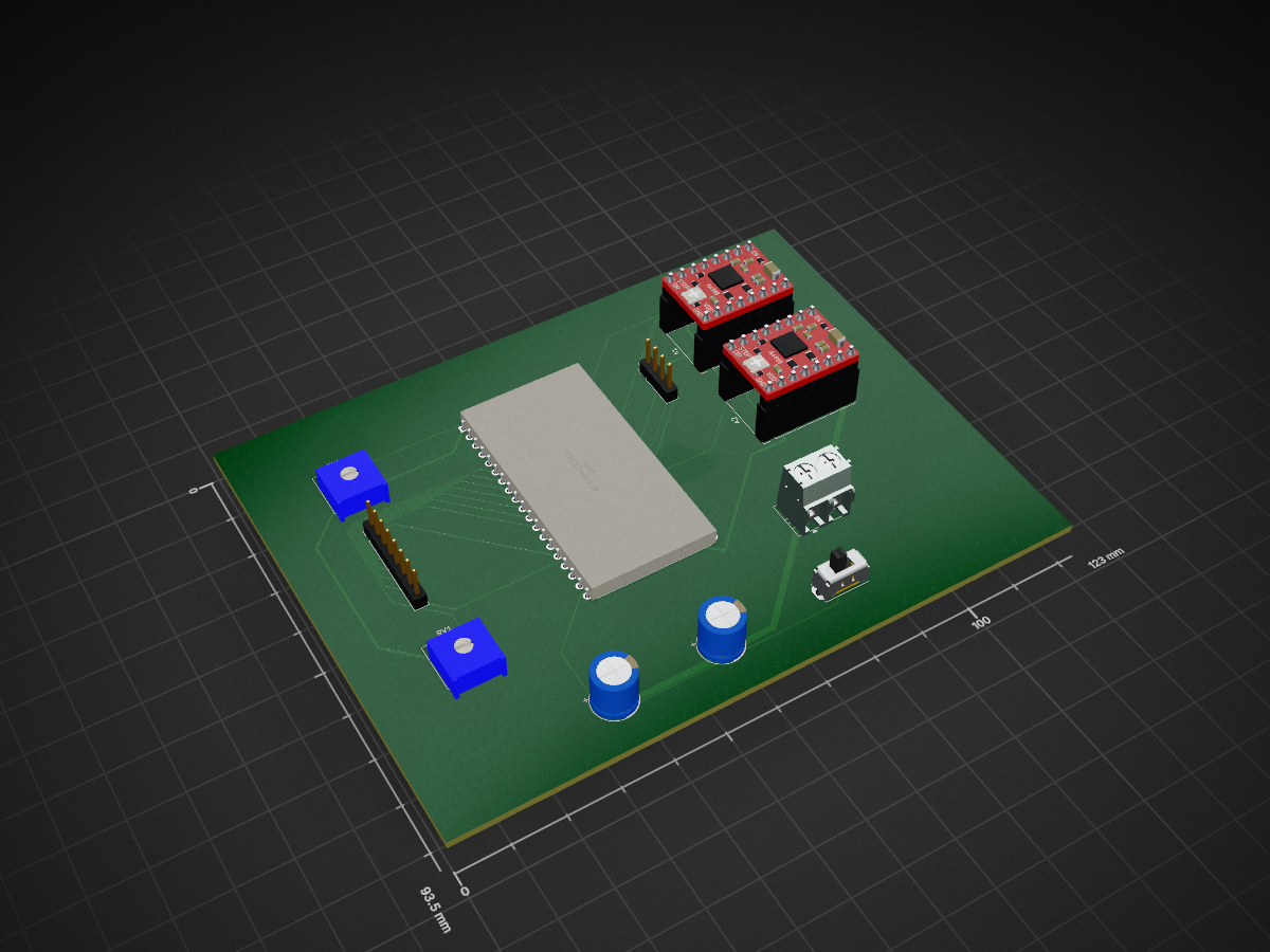
Dieless Control System is an open-source printed circuit board by Freshovsky23, from the Freshovsky23/Dieless-Control-System repository on GitHub. It is a 2-layer board of 123 × 93.5 mm with 11 parts on 55 nets, routed with 130 tracks and 0 vias.
Its parts include 3 connectors, 2 capacitors, 1 IC and 1 switch. It belongs with the robots and motor control boards and the ESP8266 boards of this library.
An advanced embedded control system designed for a Dieless Wire Drawing Machine engineering project. This system coordinates independent dual-stepper motor velocity profiles, features real-time analog micro-adjustments, and utilizes a complete local Human-Machine Interface (HMI).
Developed under the auspices of the "CREATIVE" Student Science Club.
Watch the system in action on YouTube:
Click the badge above to watch the project implementation and physical mechanical execution details.
The control system has been migrated from breadboard prototyping to a dedicated, custom-designed PCB tailored for high-frequency signal switching and heavy motor current distribution.
The board architecture implements strict physical isolation between the high-current motor power rails (VMOT) and the sensitive analog/I2C traces to completely eliminate electromagnetic interference and noise injection.
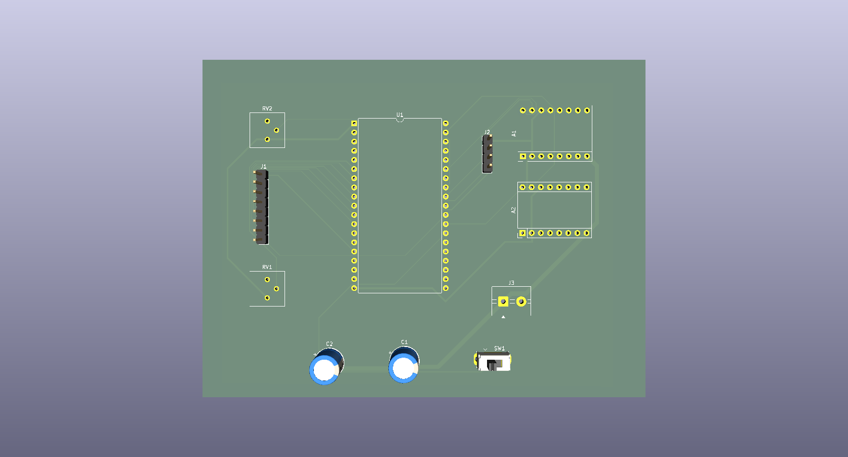
To ensure proper hardware replication, connect the peripheral components to the ESP32 microcontroller precisely as outlined in the engineering reference tables below:
| ESP32 GPIO Pin | Component Peripheral | Hardware Functionality / Description | Suggested Track Width |
|---|---|---|---|
| +5V / VIN | Main Logic Rail | Core power for driver logic and LCD module | 0.50 mm |
| +3.3V | Analog Rail | Clean reference voltage for ADC potentiometers | 0.50 mm |
| VMOT (24V) | A4988 Power Supply | High-current power for stepper motor coils | 🔥 1.20 mm |
| GND | System Common | Solid Ground Plane (Bottom Copper Zone) | Copper Zone |
| GPIO 18 | Stepper Driver 1 (A4988) | STEP – Motor 1 Pulse Generation Line (Wire Feeding) | 0.25 mm |
| GPIO 19 | Stepper Driver 1 (A4988) | DIR – Motor 1 Directional Logic Level Control | 0.25 mm |
| GPIO 23 | Stepper Driver 2 (A4988) | STEP – Motor 2 Pulse Generation Line (Wire Drawing) | 0.25 mm |
| GPIO 16 | Stepper Driver 2 (A4988) | DIR – Motor 2 Directional Control (Safe Non-Bootstrap Pin) | 0.25 mm |
| GPIO 34 | Potentiometer 1 | Analog Input – Motor 1 Real-time Speed Trim Override | 0.25 mm |
| GPIO 35 | Potentiometer 2 | Analog Input – Motor 2 Real-time Speed Trim Override | 0.25 mm |
| GPIO 4 | SPDT Toggle Switch | Digital Input (Internal Pullup) – Active Motor Selection Editor | 0.25 mm |
| ESP32 GPIO Pin | Keypad Ribbon Pin | Matrix Row / Column Designation | Suggested Track Width |
|---|---|---|---|
| GPIO 13 | Pin 1 | ROW 1 (Handles keys: 1, 2, 3, A) | 0.25 mm |
| GPIO 14 | Pin 2 | ROW 2 (Handles keys: 4, 5, 6, B) | 0.25 mm |
| GPIO 27 | Pin 3 | ROW 3 (Handles keys: 7, 8, 9, C) | 0.25 mm |
| GPIO 26 | Pin 4 | ROW 4 (Handles keys: *, 0, #, D) | 0.25 mm |
| GPIO 25 | Pin 5 | COL 1 (Handles keys: 1, 4, 7, *) | 0.25 mm |
| GPIO 33 | Pin 6 | COL 2 (Handles keys: 2, 5, 8, 0) | 0.25 mm |
| GPIO 32 | Pin 7 | COL 3 (Handles keys: 3, 6, 9, #) | 0.25 mm |
| GPIO 17 | Pin 8 | COL 4 (Handles keys: A, B, C, D) | 0.25 mm |
| ESP32 GPIO Pin | Module / Controller | Bus Line Designation | Suggested Track Width |
|---|---|---|---|
| GPIO 21 | I2C LCD 20x4 (PCF8574) | SDA – Serial Data Communication Bus | 0.25 mm |
| GPIO 22 | I2C LCD 20x4 (PCF8574) | SCL – Serial Clock Bus (Configured to 400kHz Fast Mode) | 0.25 mm |
| Key | Core Function | Operational Description |
|---|---|---|
0 – 9 | Numeric Entry | Inputs target step frequency values (Safe bounded range: 0 – 9999 Hz). |
D | Direction Stage | Toggles the pending rotational direction profile buffer layout between [CW] and [CCW]. |
# | ENTER / Commit | Flushes the staged parameters, saving target velocity and setting hardware direction pins. |
* | Backspace | Removes the terminal character from the active screen buffer string. |
C | Clear Buffer | Instantly wipes the temporary keyboard data input buffer. |
A | START Machine | Global execution trigger. Smoothly ramps up both stepper lines to target run frequencies. |
B | STOP Machine | E-Stop equivalent software override. Instantly cuts execution pulses and triggers safe deceleration. |
The user interface handles full frame updates seamlessly asynchronously. The display grid mapping topology layout runs as follows:
+------------------------------------+
|M1: [BaseHz] |T:[Trim%] |[ActiveDir]| -> Line 1: Wire Feeding Motor Telemetry
|M2: [BaseHz] |T:[Trim%] |[ActiveDir]| -> Line 2: Wire Drawing Motor Telemetry
|Input: [EditorBuffer]   [PendingDir]| -> Line 3: Live Input HMI Keypad Buffer
|[MachineStatus] | Ed: [TargetMotor] | -> Line 4: System Operational Status
+------------------------------------+
📂 Repository Structure
Plaintext
├── firmware/              # ESP32 Core Control Source Code (C++/Arduino)
│   ├── src/
│   │   └── main.cpp
│   └── platformio.ini
├── hardware/              # KiCad EDA Project Files & Manufacturing Exports
│   ├── dieless-control.kicad_pro
│   ├── dieless-control.kicad_sch
│   ├── dieless-control.kicad_pcb
│   └── Dieless.png        # 3D Render preview of the custom PCB layout
└── README.md              # Main project documentation
👤 Author
Developer: @Freshovsky23

Contact: Heilman.Wiktor23@gmail.com| Qty | Value | Footprint | References |
|---|---|---|---|
| 2 | C_Polarized | Capacitor_THT:CP_Radial_D8.0mm_P3.50mm | C1, C2 |
| 2 | Pololu_Breakout_A4988 | Module:Pololu_Breakout-16_15.2x20.3mm | A1, A2 |
| 2 | R_Potentiometer | Potentiometer_THT:Potentiometer_Bourns_3386P_Vertical | RV1, RV2 |
| 1 | AI-Thinker Nodemcu-32S | ESP32:ai-thinker nodemcu-32s | U1 |
| 1 | Conn_01x04_Pin | Connector_PinHeader_2.54mm:PinHeader_1x04_P2.54mm_Vertical | J2 |
| 1 | Conn_01x08_Pin | Connector_PinHeader_2.54mm:PinHeader_1x08_P2.54mm_Vertical | J1 |
| 1 | SW_SPDT | Button_Switch_THT:SW_Slide_SPDT_Straight_CK_OS102011MS2Q | SW1 |
| 1 | Screw_Terminal_01x02 | TerminalBlock:TerminalBlock_MaiXu_MX126-5.0-02P_1x02_P5.00mm | J3 |
google/mozc-devices
Circuit diagrams and firmware source code for Gboard DIY keyboards


FrameworkComputer/ExpansionCards
Reference designs and documentation to create Expansion Cards for the Framework Laptop

hoglet67/RGBtoHDMI
Bare-metal Raspberry Pi project that provides pixel-perfect sampling of Retro Computer RGB/YUV video and conversion to HDMI

hackclub/OnBoard
💡 Join 1,000 teenagers and make your first PCB with a $100 grant!


tardate/LittleArduinoProjects
a collection of "Little Electronic & Arduino Projects", most involving electronics or an Arduino in one way or another!

basilfx/TRADFRI-Hacking
Hacking IKEA TRÅDFRI products, such as light bulbs, window blinds and other accessories.
It measures 123 × 93.5 mm and has 2 copper layers, 1.6 mm thick.
11 parts. The full list of its parts is on this page, with links to each part's symbol and footprint where PCBKit's library has them.
From the Freshovsky23/Dieless-Control-System repository on GitHub, at the commit this page was made from: the board is hardware/PCB.kicad_pcb and its schematic hardware/PCB.kicad_sch. PCBKit opens the board in the browser, with nothing to install.
Its repository states no licence, so its author keeps all rights: ask Freshovsky23 before reusing the design.