2 layers100 × 100 mm

 FrankBuss/beat70711
A MIDI sequencer
Beat707 is an open-source printed circuit board by FrankBuss, from the FrankBuss/beat707 repository on GitHub. It is a 2-layer board of 276.9 × 142.2 mm with 276 parts on 188 nets, routed with 5,486 tracks and 137 vias.
It is built around the ATMEGA328-PU, SN74AHC125D and SN74AHCT125N, with the TM1638 and 74HC14 among its other parts. Its parts include 95 diodes, 83 resistors, 33 switches, 20 capacitors and 16 ICs. It belongs with the AVR (ATmega, ATtiny) boards of this library.


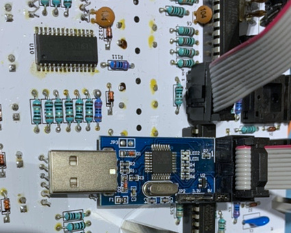
For programming you can use an USBasp. The red wire of the USBasp programmer needs to be connected to the pin 1 location:
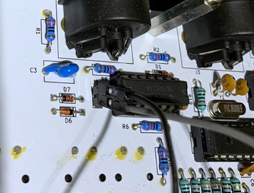
For debugging, there is the jumper J5 near the MIDI connector, to connect a 5V UART receiver. Connect the top pin to GND (black wire in the image) and the bottom pin to the UART RX input (grey wire) :
The Arduino IDE doesn't flash the ATmega fuses, so initially you need to do this from the command line with avrdude like this:
avrdude -cusbasp -p m328 -B 10 -U lfuse:w:0xff:mThe output should look like this:
avrdude: set SCK frequency to 93750 Hz
avrdude: AVR device initialized and ready to accept instructions

Reading | ################################################## | 100% 0.00s

avrdude: Device signature = 0x1e9514 (probably m328)
avrdude: reading input file "0xff"
avrdude: writing lfuse (1 bytes):

Writing | ################################################## | 100% 0.00s

avrdude: 1 bytes of lfuse written
avrdude: verifying lfuse memory against 0xff:
avrdude: load data lfuse data from input file 0xff:
avrdude: input file 0xff contains 1 bytes
avrdude: reading on-chip lfuse data:

Reading | ################################################## | 100% 0.00s

avrdude: verifying ...
avrdude: 1 bytes of lfuse verified

avrdude: safemode: Fuses OK (E:FF, H:D9, L:FF)

avrdude done. Thank you.First install the Arduino IDE. It was tested with Arduino 1.8.13. Then add the URL https://mcudude.github.io/MiniCore/package_MCUdude_MiniCore_index.json to "File->Preferences->Settings->Additional Board Manager URLs". Then you can install the new board with "Tools->Board->Boards Manager". Install "MiniCore by MCUdude", tested with version 2.1.0.
For programming you need an USBasp. You need to reduce the clock speed in the file /home/username/bin/arduino-1.8.9/hardware/arduino/avr/programmers.txt, where username is your username (on Linux, on Windows and Mac it might be different, see here). Search for the usbasp.program.extra_params line and add the parameter -B 10. The full line now looks like this:
usbasp.program.extra_params=-Pusb -B 10Restart the Arduino IDE after changing it.
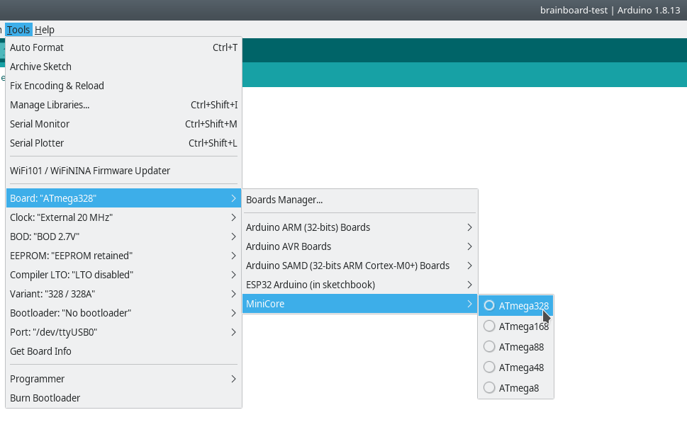
After restart, select the new board: Tools->Board->MiniCore->ATmega328. For flashing the firmware, configure the following settings (Board, Clock, Variant and Bootloader needs to be changed):
Then select your programmer, for example USBasp:
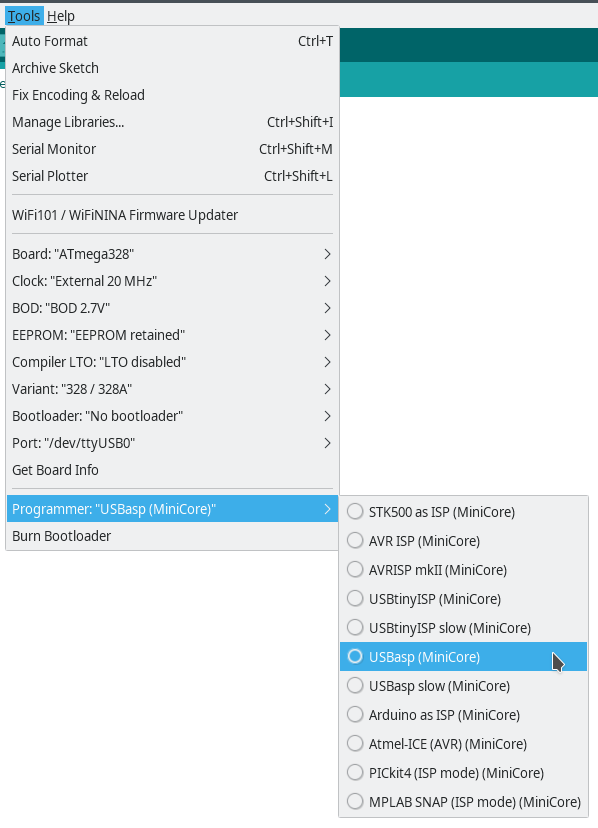
After this you can program the ATmega328 on the board from the Arduino IDE by clicking on the right arrow.
| Qty | Value | Footprint | References |
|---|---|---|---|
| 59 | 1N4148 | Diode_THT:D_DO-35_SOD27_P7.62mm_Horizontal | D1, D10, D11, D12, D104, D105, D106, D107, D116, D117, D118, D119, D120, D121, D122, D123 +43 |
| 36 | LED | LED_THT:LED_D3.0mm | D32, D33, D34, D35, D100, D101, D102, D103, D108, D109, D110, D111, D112, D113, D114, D115 +20 |
| 32 | SW_Push | beat707:B3F-through-hole | SW18, SW19, SW20, SW21, SW22, SW23, SW24, SW25, SW42, SW43, SW44, SW45, SW46, SW47, SW48, SW49 +16 |
| 24 | 10 | Resistor_THT:R_Axial_DIN0207_L6.3mm_D2.5mm_P10.16mm_Horizontal | R51, R52, R53, R54, R55, R56, R57, R58, R121, R122, R123, R124, R125, R126, R127, R128 +8 |
| 20 | 220 | Resistor_THT:R_Axial_DIN0207_L6.3mm_D2.5mm_P10.16mm_Horizontal | R1, R2, R3, R4, R10, R11, R25, R26, R30, R31, R32, R33, R40, R41, R110, R111 +4 |
| 19 | 10k | Resistor_THT:R_Axial_DIN0207_L6.3mm_D2.5mm_P10.16mm_Horizontal | R12, R13, R14, R15, R16, R17, R18, R19, R20, R21, R22, R23, R24, R50, R120, R139 +3 |
| 12 | MountingHole | MountingHole:MountingHole_3.2mm_M3 | H1, H2, H3, H4, H5, H6, H7, H8, H9, H10, H11, H12 |
| 9 | 100nF | Capacitor_THT:C_Disc_D3.0mm_W2.0mm_P2.50mm | C2, C4, C6, C7, C14, C15, C16, C17, C18 |
| 8 | 0 | Resistor_THT:R_Axial_DIN0207_L6.3mm_D2.5mm_P10.16mm_Horizontal | R102, R103, R104, R105, R106, R107, R108, R109 |
| 8 | 1nF | Capacitor_THT:C_Disc_D8.0mm_W5.0mm_P7.50mm | C1, C3, C8, C9, C10, C11, C19, C20 |
| 8 | 33 | Resistor_THT:R_Axial_DIN0207_L6.3mm_D2.5mm_P10.16mm_Horizontal | R137, R138, R140, R141, R142, R143, R144, R145 |
| 6 | CA56-12EWA | Display_7Segment:CA56-12EWA | U5, U6, U8, U9, U11, U12 |
| 6 | free IO | Connector_PinHeader_2.54mm:PinHeader_1x01_P2.54mm_Vertical | J9, J10, J12, J13, J14, J15 |
| 4 | 1k | Resistor_THT:R_Axial_DIN0207_L6.3mm_D2.5mm_P10.16mm_Horizontal | R5, R27, R28, R29 |
| 3 | TM1638 | Package_SO:SOIC-28W_7.5x17.9mm_P1.27mm | U4, U7, U10 |
| 2 | 22pF | Capacitor_THT:C_Disc_D3.0mm_W2.0mm_P2.50mm | C12, C13 |
| 1 | +5V | Connector_PinHeader_2.54mm:PinHeader_1x01_P2.54mm_Vertical | J6 |
| 1 | 20 MHz | Crystal:Crystal_HC49-U_Vertical | Y1 |
| 1 | 47uF | Capacitor_THT:CP_Radial_D6.3mm_P2.50mm | C5 |
| 1 | 6N138 | Package_DIP:DIP-8_W7.62mm | U1 |
| 1 | 74HC14 | Package_DIP:DIP-14_W7.62mm | U2 |
| 1 | ATmega328-PU | Package_DIP:DIP-28_W7.62mm | U3 |
| 1 | GND | Connector_PinHeader_2.54mm:PinHeader_1x01_P2.54mm_Vertical | J7 |
| 1 | ISP | Connector_PinHeader_2.54mm:PinHeader_2x05_P2.54mm_Vertical | J11 |
| 1 | LP2950CZ-3.3G | Package_TO_SOT_THT:TO-92_Inline | U15 |
| 1 | Logo_Open_Hardware_Small | Symbol:OSHW-Logo_19x20mm_SilkScreen | LOGO1 |
| 1 | MB85RS2MT | Package_DIP:DIP-8_W7.62mm | U14 |
| 1 | MIDI-in | beat707:din-5 | J3 |
| 1 | MIDI-out | beat707:din-5 | J4 |
| 1 | Rotary_Encoder_Switch | Rotary_Encoder:RotaryEncoder_Alps_EC11E-Switch_Vertical_H20mm | SW1 |
| 1 | SN74AHC125 | Package_DIP:DIP-14_W7.62mm | U13 |
| 1 | SN74AHCT125 | Package_DIP:DIP-14_W7.62mm | U16 |
| 1 | USB_B | Connector_USB:USB_B_OST_USB-B1HSxx_Horizontal | J8 |
| 1 | click-out | beat707:trs | J2 |
| 1 | footswitch | beat707:trs | J1 |
| 1 | serial debug | Connector_PinHeader_2.54mm:PinHeader_2x01_P2.54mm_Vertical | J5 |


cs2dsb/coffee_assistant
Free and open source software distributed under the terms of both the [MIT License][lm] and the [Apache License 2.0][la].

georgsnarbuts/kalkulators
A mechanical-key calculator that also works as a numpad, designed and sold as a kit.


klein0r/pcb-ws2812-wifi-controller
WiFi Controller for WS2812 LED Stripes


klein0r/pcb-ws2812-ethernet-controller
Ethernet Controller for WS2812 LED Stripes
It measures 276.9 × 142.2 mm and has 2 copper layers, 1.6 mm thick.
276 parts, built around the ATMEGA328-PU, SN74AHC125D, SN74AHCT125N and TM1638. The full list of its parts is on this page, with links to each part's symbol and footprint where PCBKit's library has them.
From the FrankBuss/beat707 repository on GitHub, at the commit this page was made from: the board is kicad/beat707/beat707.kicad_pcb. PCBKit opens the board in the browser, with nothing to install.
Its repository states no licence, so its author keeps all rights: ask FrankBuss before reusing the design.